Monochrome Display Adapter: Notes
This document describes the behaviour of IBM's original Monochrome Display Adapter and some compatible cards.
The MDA is a monochrome card and displays on a TTL monochrome monitor. The original IBM mono monitor has green phosphor, so that's the colour I'll use when describing its behaviour. MDA monitors also exist with amber and white phosphor.
An alternative acronym for this card is MDPA (Monochrome Display and Printer Adapter).
- Hardware requirements
- The hardware
- Memory Map
- Register I/O
- High Resolution Mode
- The printer port
- Colour MDA
- MDA Clones
Hardware requirements
The original MDA is a full-length 8-bit ISA card containing the display controller and a printer port. When present in a computer, it requires the following system resources:
- 4k of RAM at address 0B0000h for its display buffer. This address is not completely decoded; the entire 32k from 0B0000h to 0B7FFFh is filled with repeats of this 4k area.
- I/O addresses 03B0h-03BFh.
- The printer port uses IRQ7.
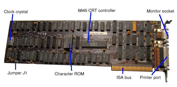
The hardware
The MDA is based on an MC6845 cathode ray tube controller (CRTC) plus a lot of discrete logic. The two big chips on an MDA are the 6845 (soldered on) and the character generator ROM (usually socketed). Since the character set is in ROM, the only way you'll get a different one is with a new ROM.
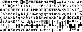
The character ROM contains not only a 14-row font for normal operation, but two 8x8 fonts (one with thin uprights, the other with thick ones). This is because the same ROM is used on CGA cards; the 8x8 fonts are not displayed by the MDA.
Note that the character ROM is a 9264, which has a different pinout from the normal 27xx chip range (2764, 27128 etc.). This USENET posting describes how to get a 2764 ROM to work in a 9264 socket (it refers to the 5150 PC motherboard, but the pinout is the same for the MDA and CGA cards). Because the pinout is the same, it's possible to read the character ROM from an MDA or CGA by plugging it into the spare ROM socket on a 5150 motherboard.
Output is from a DE9 socket. The pinout of this socket is:
- Ground
- Ground
- Not connected
- Not connected
- Not connected
- High intensity
- Video
- Horizontal sync
- -Vertical sync
There is a single jumper (J1). In normal use, this is left open. It is probably used for diagnostic testing; if it is closed:
- The clock crystal is disabled; clock input comes from pin 4 of chip U24, which is not connected to anything.
- The character clock is stopped.
- The underline attribute is forced on.
- The VSYNC signal is (I think) disabled.
This appears to be used to isolate some of the card's subsystems from each other, for testing.
Memory Map
In normal use, an MDA produces an 80x25 text screen. Each character is 9 pixels wide and 14 high, giving a 720x350 pixel resolution. Although the characters are 9 pixels wide, the bitmaps in the ROM are only 8 pixels. For characters C0h-DFh, the ninth pixel column is a duplicate of the eighth; for others, it's blank.
The memory storage scheme is that two bytes of video RAM are used for each character (80*25*2 = 4000, neatly fitting in the 4k RAM on the card). The first byte is the character code, and the second gives the attribute.
Character codes match whatever the font ROM in use is. Normally this is 'codepage 437' - ASCII plus a collection of accented characters, line graphics and a few other characters.
The attribute bytes mostly behave like a bitmap:
- Bit 1: Underline.
- Bit 3: High intensity.
- Bit 7: Blink
but there are eight exceptions:
- Attributes 00h, 08h, 80h and 88h display as black space.
- Attribute 70h displays as black on green.
- Attribute 78h displays as dark green on green. In fact, depending on timing and on the design of the monitor, it may have a bright green 'halo' where the dark green and bright green bits meet.
- Attribute F0h displays as a blinking version of 70h (if blinking is enabled); as black on bright green otherwise.
- Attribute F8h displays as a blinking version of 78h (if blinking is enabled); as dark green on bright green otherwise.
| 00 | 01 | 02 | 03 | 04 | 05 | 06 | 07 | 08 | 09 | 0A | 0B | 0C | 0D | 0E | 0F | 10 | 11 | 12 | 13 | 14 | 15 | 16 | 17 | 18 | 19 | 1A | 1B | 1C | 1D | 1E | 1F |
| 20 | 21 | 22 | 23 | 24 | 25 | 26 | 27 | 28 | 29 | 2A | 2B | 2C | 2D | 2E | 2F | 30 | 31 | 32 | 33 | 34 | 35 | 36 | 37 | 38 | 39 | 3A | 3B | 3C | 3D | 3E | 3F |
| 40 | 41 | 42 | 43 | 44 | 45 | 46 | 47 | 48 | 49 | 4A | 4B | 4C | 4D | 4E | 4F | 50 | 51 | 52 | 53 | 54 | 55 | 56 | 57 | 58 | 59 | 5A | 5B | 5C | 5D | 5E | 5F |
| 60 | 61 | 62 | 63 | 64 | 65 | 66 | 67 | 68 | 69 | 6A | 6B | 6C | 6D | 6E | 6F | 70 | 71 | 72 | 73 | 74 | 75 | 76 | 77 | 78 | 79 | 7A | 7B | 7C | 7D | 7E | 7F |
| 80 | 81 | 82 | 83 | 84 | 85 | 86 | 87 | 88 | 89 | 8A | 8B | 8C | 8D | 8E | 8F | 90 | 91 | 92 | 93 | 94 | 95 | 96 | 97 | 98 | 99 | 9A | 9B | 9C | 9D | 9E | 9F |
| A0 | A1 | A2 | A3 | A4 | A5 | A6 | A7 | A8 | A9 | AA | AB | AC | AD | AE | AF | B0 | B1 | B2 | B3 | B4 | B5 | B6 | B7 | B8 | B9 | BA | BB | BC | BD | BE | BF |
| C0 | C1 | C2 | C3 | C4 | C5 | C6 | C7 | C8 | C9 | CA | CB | CC | CD | CE | CF | D0 | D1 | D2 | D3 | D4 | D5 | D6 | D7 | D8 | D9 | DA | DB | DC | DD | DE | DF |
| E0 | E1 | E2 | E3 | E4 | E5 | E6 | E7 | E8 | E9 | EA | EB | EC | ED | EE | EF | F0 | F1 | F2 | F3 | F4 | F5 | F6 | F7 | F8 | F9 | FA | FB | FC | FD | FE | FF |
Register I/O
03B0h, 03B2h, 03B4h, 03B6h: CRTC address register.
Write a CRTC register number (0 to 11h) to this port to select the CRTC register that will appear at port 03B5h. For details of the registers, see the 6845 datasheet.
These addresses are partially decoded on a real MDA, so that any even- numbered address between 03B0h and 03B7h will get you the CRTC address register. But the official register to use is 03B4h.
This is a write-only register.
03B1h, 03B3h, 03B5h, 03B7h: CRTC register read/write.
This gives access to the selected CRTC data register. Most CRTC registers are write only; some are read/write or read-only. As with the address register, this is partially decoded; so although the official address is port 03B5h, it also appears at the other odd-numbered addresses between 03B0h and 03B7h.
03B8h: Mode Control Register
On a genuine MDA, this is a write-only register. Four of its bits can be set, but only two are any use:
Bit 5: 1 to enable blinking, 0 to disable it.
If bit 5 is 1, characters with attribute bit 7 set will blink. If not, they will have high intensity background.
Bit 3: 1 to enable video output, 0 to disable it.
If bit 3 is 0, screen output will not be shown. The usual use of this is if you're reprogramming the CRTC registers; disable video output beforehand and re-enable it after.
Bit 1: 1 for black and white.
This bit has no meaning, since the MDA always outputs in monochrome. The value written to it is stored (in chip U58) but nothing else on the card pays any attention to it.
Bit 0: 1 for high resolution mode.
For any sane purpose this bit must be set to 1. For details of what happens if it is set to zero, see High Resolution Mode.
Quite why the MDA implements bits 0 and 1 is not clear. Possibly IBM originally planned to make an expanded MDA that supported 40 columns and/or colour; or perhaps the CGA was designed first, and the MDA was based on the CGA design, including vestiges of the CGA's 40-column and colour support. See also colour MDA.
03BAh: Status Register
This is a read-only register. Only two bits of the value read from this port are defined:
- Bit 3: Video. This is 1 if a green or bright green pixel is being drawn on the screen at this moment.
- Bit 0: Retrace. This is 1 if the horizontal retrace is active.
(On a real IBM MDA, bits 7-4 are always 1, and bits 2-1 are always 0).
High Resolution Mode
According to IBM's technical manual (page 1-128), setting bit 0 of port 03B8h to 1 puts the MDA into "high-resolution mode". One might therefore deduce that setting it to 0 selects a "low-resolution mode". This is not the case.
Page 1-125 of the same manual warns:
To ensure proper initialization, the first command issued to the attachment must be to send to CRT control port 1 (hex 3B8), a hex 01, to set the high-resolution mode. If this bit is not set, then the processor access to the monochrome adapter must never occur. If the high-resolution bit is not set, the processor will stop running.
That is, if you take an MDA out of high-resolution mode, then any attempt to access its ports or memory could well cause the computer to hang.
If a zero is written to bit 0 of port 03B8h, the following MDA functions change:
- The 16.257MHz pixel clock (connected to pin 6 of chip U24) is not used. Instead, the pixel clock is taken from pin 5 of U24. This pin is connected only to a solder pad beside the clock crystal. This explains IBM's warning above. The pixel clock is used (among other things) to pause the PC's processor if it tries to access the MDA while the screen is being drawn; so if the pixel clock is stopped, that might stop the processor dead as well.
- Characters can only be up to 8 pixels high; high resolution allows up to 16 pixels high (normally 14 is used).
- If jumper 1 is fitted, then the pixel clock is taken from pin 3 of U24, which on a normal MDA is connected to Ground.
- Jumper 1 also selects which 8x8 font is used. Rather unfortunately, this conflicts with all the other functions of jumper 1.
From top to bottom, the four solder pads beside the clock crystal (in the middle of this picture) are:
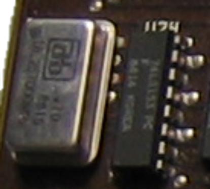
- Ground
- ~ High Resolution
- Ground
- Clock input? (U24 pin 5)
This suggests that the intention was to have a 4-pin header on these pads for a second clock crystal (or other timing source) to be connected - or, possibly, to replace the existing crystal with one that could provide two different clock signals. This would then have provided a suitable pixel clock for a low-resolution text display.
The printer port
The printer port on a genuine IBM MDA behaves as follows:
- Write to port 03BCh: Set data lines.
- Read from port 03BCh: Reads last value sent to printer. If the printer is trying to drive the data lines (which the manual says it mustn't do) then this will be ORed with the last value written.
- Read from port 03BDh: Get printer status.
- Bit 3: ~Error
- Bit 4: Select
- Bit 5: Paper out
- Bit 6: ~Acknowledge
- Bit 7: Busy
- Write to port 03BEh: Set control lines.
- Bit 0: ~Strobe
- Bit 1: ~Auto Feed
- Bit 2: Initialize printer
- Bit 3: ~Select input
- Bit 4: Enable interrupt when the printer sets ~Acknowledge to 0.
- Read from port 03BEh: Reads last value sent to port 03BEh. As with port 03BCh, if the printer is driving these lines, the value will be ORed with the last value written. Bits 5,6,7 are undefined; on a real MDA, they are always 1.
Colour MDA
According to Programmer's Guide To PC And PS/2 Video Systems (by Richard Wilton, ISBN 1-55615-103-9), some IBM MDA cards included support for colour monitors:
Surprisingly, a few IBM MDAs generate color as well as monochrome output. Of course, the MDA's green monochrome display uses only two signals to control attributes (video on/off and intensity on/off); it ignores any color video signals. However, a color display that can use the MDA's 16.257 MHz horizontal sync and 50Hz vertical sync signals will display eight colors (with and without intensity) when attached to some (but not all) MDAs. Unfortunately, you can never be certain which MDA will turn out to be a color adapter in disguise.
I have no further information on this subject.
MDA Clones
Up to this point, I've concentrated on the genuine IBM MDA. This section gives a brief tour of how various MDA clones and supersets behave.
General notes
The "high resolution" bit (bit 0) of port 3B8h is nearly always ignored, and most cards work fine with it set to zero.
The undefined bits of port 3BAh may not be the same combination of zeroes and ones that they are on a real MDA; they may be all zeroes, for example. For Hercules-compatible cards (which are a superset of MDA), bit 7 is a vertical sync signal (1 when the screen is being drawn, 0 in the vertical blanking interval) and bit 1 returns lightpen status.
On a real MDA, the memory between B1000h and B7FFFh is filled with copies of B0000h - B0FFFh. Some clones (particularly Hercules cards) actually have 32k of RAM; others emulate the behaviour of a real MDA. I haven't yet seen an MDA clone that doesn't have anything between B1000h and B7FFFh, but that doesn't mean there isn't one.
Some MDA clones don't support dark and/or bright colours; they end up restricted to just normal, or normal plus bright.
3270 PC
The 3270 PC's video card supports programs which treat it as an MDA - either on its own colour monitor, or on a mono monitor. The resolution is the same as a normal MDA (720x350) but the font used is based on the 3270 terminal rather than the original MDA.
On a mono monitor, the attributes displayed are not quite the same as on a real MDA:
- 77h and F7h display as solid green.
- 7Fh and FFh display as solid bright green.
- Only 01h, 09h, 81h and 89h are underlined.
- 78h and F8h display as black on bright green, rather than dark green on normal green.
On a mono monitor, only one bit in the MDA mode control register has any effect - bit 5 (enable/disable blink). The others are ignored.
The video RAM repeats at 4k intervals all the way from 0B0000h to 0BFFFFh.
On a colour monitor, the attributes in MDA mode act as colours (bits 0-2=foreground, bits 4-6=background, bit 7=blink).
The extra video mode 30h (720x350 graphics) can be used on an MDA monitor. So can the 3270 emulation features.
Amstrad PPC / PC20
The Amstrad PPC has a chipset that can emulate MDA or CGA - either driving a normal monitor, or its internal LCD. The desktop version (PC20 aka Sinclair PC200) uses a similar system, but only supports an external monitor.
- On LCDs, the screen resolution is 640x200. The 8x8 CGA font is used. High intensity is simulated by 'eroding' characters to make them look thin. Underlining is not supported, and if blinking is turned off, there is no alternative special effect.
- On a monitor, the resolution is 640x350. The ninth column of characters is not drawn. In addition, the text attributes are not quite the same as on a real MDA. Attributes 08h and 88h display just like 18h and 98h, as bright green on black (on a real MDA, these would not display). Conversely, attributes 40h and 0C0h do not display, whereas a real MDA would display them in green on black.
- There is no Hercules support. The top 4 bits of port 3BAh always read 0, and the display RAM does repeat at 4k intervals.
- There is a NMI system which catches attempts to reprogram the MDA and hands them over to the BIOS. This is so that programs which try to change mode by manually altering CRTC registers still work despite the different CRTC values used by the LCD.
Hercules
Most MDA clones implement some form of Hercules-compatible graphics. The main differences for a Hercules-compatible card are:
- Writing to port 03BFh enables extra bits in the Mode Control
register at 03B8h:
- Set bit 0 of 3BFh to enable bit 1 of 3B8h
- Set bit 1 of 3BFh to enable bit 7 of 3B8h and the second 32k of RAM ("Full" mode).
- Writing to port 03B8h has these extra effects (assuming the
appropriate bits have previously been enabled):
- If bit 1 is set, graphics mode is selected.
- If bit 7 is set, the graphics frame buffer is at 0B8000h. Otherwise it's at 0B000h.
- In "full" mode, a Herc card occupies memory between 0B0000h and 0BFFFFh, for two frame buffers. In "half" mode, only one frame buffer is present, from 0B0000h to 0B7FFFh; this allows the card to be used in a dual-head configuration.
- Reading from port 03BAh returns vertical sync in bit 7, and
a card ID in bits 6-4:
- 000: Hercules
- 001: Hercules Plus
- 101: Hercules InColor
- 111: Unknown clone (see below)
- Some Hercules cards support a light pen. Bit 1 of port 3BAh returns the lightpen sensor status; any write to port 3BBh resets the light pen status.
One card I have encountered, which appears to be a Hercules clone of Eastern European origin, has a further capability - two ROM fonts, selectable in software. These options are controlled in a similar manner to other extended features in the Hercules: Bit 2 of port 3BFh must be set to enable the feature, and then Bit 4 of port 3B8h selects which font to use. The card ID in bits 6-4 of port 03BAh has all three bits set.
John Elliott 6 November 2005