PPC / PC20 display notes
The PPC and PC20/PC200 use very similar video hardware - an internal display adaptor (IDA) that supports CGA and MDA modes. The MDA is at a reduced resolution; IBM's original uses 720x350, while the PPC and PC20/PC200 use 640x350 for external monitors and 640x200 for the internal LCD (PPC only).
PPC display limitations
The PPC's internal display is a mono 640x200 LCD. It emulates the various video modes like this:
MDA text mode
- Characters are 8x8, rather than 8x14 as on a genuine MDA.
- High intensity characters are 'eroded' to look thin. Each byte of the character bitmap becomes (byte & (byte >> 1)).
- If blinking characters are disabled, there is no alternative special effect.
- There is no underlining.
Here are the text attributes used by the PPC / PC200 with an external MDA monitor:
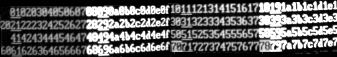
as opposed to the attributes used by a genuine MDA:
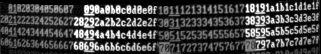
(The poor quality of the pictures is caused by the use of a cheap webcam).
CGA text modes
- Colours are mapped to foreground/background combinations.
- The "intensity" and "blink" bits work the same way as in MDA mode.
- There is an option - "LCD text contrast" which switches between two alternative mappings between the CGA colours and LCD foreground/background. The supplied LCD.COM allows the user to switch between them using the ALTGR key.
- The undocumented 160x100 "graphics" mode is emulated. In this mode, the 80 attribute bytes for a row are displayed as the bitmap for that row.
| CGA to LCD colours (first mapping) | |||||||||||||||
| 00 | 01 | 02 | 03 | 04 | 05 | 06 | 07 | 08 | 09 | 0A | 0B | 0C | 0D | 0E | 0F |
| 10 | 11 | 12 | 13 | 14 | 15 | 16 | 17 | 18 | 19 | 1A | 1B | 1C | 1D | 1E | 1F |
| 20 | 21 | 22 | 23 | 24 | 25 | 26 | 27 | 28 | 29 | 2A | 2B | 2C | 2D | 2E | 2F |
| 30 | 31 | 32 | 33 | 34 | 35 | 36 | 37 | 38 | 39 | 3A | 3B | 3C | 3D | 3E | 3F |
| 40 | 41 | 42 | 43 | 44 | 45 | 46 | 47 | 48 | 49 | 4A | 4B | 4C | 4D | 4E | 4F |
| 50 | 51 | 52 | 53 | 54 | 55 | 56 | 57 | 58 | 59 | 5A | 5B | 5C | 5D | 5E | 5F |
| 60 | 61 | 62 | 63 | 64 | 65 | 66 | 67 | 68 | 69 | 6A | 6B | 6C | 6D | 6E | 6F |
| 70 | 71 | 72 | 73 | 74 | 75 | 76 | 77 | 78 | 79 | 7A | 7B | 7C | 7D | 7E | 7F |
| 80 | 81 | 82 | 83 | 84 | 85 | 86 | 87 | 88 | 89 | 8A | 8B | 8C | 8D | 8E | 8F |
| 90 | 91 | 92 | 93 | 94 | 95 | 96 | 97 | 98 | 99 | 9A | 9B | 9C | 9D | 9E | 9F |
| A0 | A1 | A2 | A3 | A4 | A5 | A6 | A7 | A8 | A9 | AA | AB | AC | AD | AE | AF |
| B0 | B1 | B2 | B3 | B4 | B5 | B6 | B7 | B8 | B9 | BA | BB | BC | BD | BE | BF |
| C0 | C1 | C2 | C3 | C4 | C5 | C6 | C7 | C8 | C9 | CA | CB | CC | CD | CE | CF |
| D0 | D1 | D2 | D3 | D4 | D5 | D6 | D7 | D8 | D9 | DA | DB | DC | DD | DE | DF |
| E0 | E1 | E2 | E3 | E4 | E5 | E6 | E7 | E8 | E9 | EA | EB | EC | ED | EE | EF |
| F0 | F1 | F2 | F3 | F4 | F5 | F6 | F7 | F8 | F9 | FA | FB | FC | FD | FE | FF |
| CGA to LCD colours (second mapping) | 00 | 01 | 02 | 03 | 04 | 05 | 06 | 07 | 08 | 09 | 0A | 0B | 0C | 0D | 0E | 0F | 10 | 11 | 12 | 13 | 14 | 15 | 16 | 17 | 18 | 19 | 1A | 1B | 1C | 1D | 1E | 1F | 20 | 21 | 22 | 23 | 24 | 25 | 26 | 27 | 28 | 29 | 2A | 2B | 2C | 2D | 2E | 2F | 30 | 31 | 32 | 33 | 34 | 35 | 36 | 37 | 38 | 39 | 3A | 3B | 3C | 3D | 3E | 3F | 40 | 41 | 42 | 43 | 44 | 45 | 46 | 47 | 48 | 49 | 4A | 4B | 4C | 4D | 4E | 4F | 50 | 51 | 52 | 53 | 54 | 55 | 56 | 57 | 58 | 59 | 5A | 5B | 5C | 5D | 5E | 5F | 60 | 61 | 62 | 63 | 64 | 65 | 66 | 67 | 68 | 69 | 6A | 6B | 6C | 6D | 6E | 6F | 70 | 71 | 72 | 73 | 74 | 75 | 76 | 77 | 78 | 79 | 7A | 7B | 7C | 7D | 7E | 7F | 80 | 81 | 82 | 83 | 84 | 85 | 86 | 87 | 88 | 89 | 8A | 8B | 8C | 8D | 8E | 8F | 90 | 91 | 92 | 93 | 94 | 95 | 96 | 97 | 98 | 99 | 9A | 9B | 9C | 9D | 9E | 9F | A0 | A1 | A2 | A3 | A4 | A5 | A6 | A7 | A8 | A9 | AA | AB | AC | AD | AE | AF | B0 | B1 | B2 | B3 | B4 | B5 | B6 | B7 | B8 | B9 | BA | BB | BC | BD | BE | BF | C0 | C1 | C2 | C3 | C4 | C5 | C6 | C7 | C8 | C9 | CA | CB | CC | CD | CE | CF | D0 | D1 | D2 | D3 | D4 | D5 | D6 | D7 | D8 | D9 | DA | DB | DC | DD | DE | DF | E0 | E1 | E2 | E3 | E4 | E5 | E6 | E7 | E8 | E9 | EA | EB | EC | ED | EE | EF | F0 | F1 | F2 | F3 | F4 | F5 | F6 | F7 | F8 | F9 | FA | FB | FC | FD | FE | FF |
CGA graphics modes
- 320x200 mode is the same as 640x200 mode, so that what would be coloured areas show up as shaded.
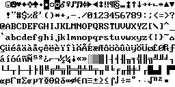
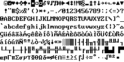
Display Fonts
Here are the fonts used by the PPC/PC20 IDA.
The CGA characters used in text mode (from the CGA font ROM) are aligned to the right-hand side of the character cell; in graphics mode (from the ROS ROM), they are aligned to the left-hand side.
| Character set | CGA | MDA |
|---|---|---|
| Normal |  |
 |
| Danish |  |
 |
| Portugese | 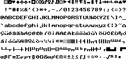 |
 |
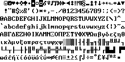
| Greek | 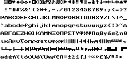 |
 |
Technical information
The IDA on a PPC or PC20/PC200 is designed to disallow direct access to some video controller registers. Attempts to write to these registers will cause a non-maskable interrupt; the NMI handler then programs the registers itself, using a table of preset values. This means that programs which attempt to change video mode by programming the video controller directly may still work on an LCD or television.
The way this works on the PPC is fully documented in the technical manual, section 1.11; in particular, 1.11.5.6 and following sections.
To support this, the IDA has some extra registers, and extra bits in existing registers:
CGA Mode Control Register: 03D8h (CGA)
- Bits 0-5 of this register retain their standard meanings.
- Bit 6 is set to select the 160x100 "graphics" mode.
- Bit 7 is set to select the alternative colour mapping (LCD text contrast).
Bits 6 and 7 are protected by the IDA; attempts to write to them will usually trigger an NMI.
On a genuine CGA, this register is write-only. On a PPC / PC200, it can be read (this returns the last value written).
Graphics Adaptor interrupt status: 03DDh
This is a read-only port which gives the reason why the graphics adaptor raised a non-maskable interrupt. Reading this port clears the top 3 bits.
- Bit 7 is set if a value has been written to the mode control register.
- Bit 6 is set if a value has been written to port 03DEh.
- Bit 5 is set if a value has been written to a 6845 register (port 03D5h).
- Bits 0-4 give the last 6845 register number written to port 03B4h/03D4h.
Operation control register: 03DEh
Reading this port reads the first three motherboard DIP switches:
- Bits 0-2: Bits 0-2 of last value written to this port.
- Bit 3: Switch 1
- Bit 4: Switch 2
- Bit 5: Switch 3
- Bits 6-7: Bits 6-7 of last value written to this port.
Writing to the port controls the extended video hardware:
- Bit 0: Set to 1 to output to an external monitor, 0 to use the builtin LCD (on a PPC) or television modulator (PC200).
- Bit 1: Set to 1 to emulate an MDA, 0 to emulate a CGA.
- Bit 2: Set to 1 to disable internal display adaptor.
- Bits 3-5: Not used.
- Bit 6: Set to 1 to unlock the video controller, 0 to lock it. If the video controller is locked, CRTC registers R0-R11 and bits 6-7 of port 03D8h cannot be written.
- Bit 7: Set to 1 to raise an NMI if an attempt is made to write to a locked display register.
The last value written to this port is saved at 0040:008Fh (PPC) or 0040:008Eh (PC20/PC200).
Last 6845 value written: 03DFh
Port 03DFh is a read-only port, which returns the last value written to port 03B5h/03D5h.
Video NMI
When a program attempts to program the graphics hardware directly, by writing to:
- The mode control register (port 03B8h/03D8h);
- The 6845 (port 03B5h/03D5h);
- The operation control register (port 03DEh)
- and the I/O channel check is enabled (bit 5 of port 061h), then an NMI will be raised. The ROS will do the following:
- Check if 0040:0089h is zero. If it is, then set it to 0FFh; otherwise return. This prevents the handler being re-entered.
- The top 2 bits of port 62h are checked. If this is not a parity error or I/O channel check, the ROS jumps to the previous NMI handler.
- If this is a parity error, the system halts with an error message.
- Port 03DDh is read. If the top 3 bits are zero, then the video hardware did not cause the NMI, so jump to the previous NMI handler (its address is at 0040:008Ah). The value that was read is retained for later use.
- The last value written to port 03DEh is loaded. Bit 6 is set (unlock the IDA), and bits 7 and 2 are reset (disable NMI, and enable the IDA). The resulting value is output to port 03DEh.
- If bit 5 of port 03DDh was set, then handle output to a 6845 register:
- (PPC only) If the write was to R10 or R11 (cursor start / cursor end) and the display is in MDA mode and the LCD is in use, the low 5 bits of the value are restricted to between 0 and 7. This ensures that the cursor will fit in the 8x8 character cells used by the LCD.
- If register R1 (Horizontal Displayed) is written, then look up the correct values for registers R0-R3 from a ROM table and output them. The correct values depend what video mode is in use, and what the output device is. (PPC only) If R1 is set to 80 and the display is in CGA mode, set bit 0 of 0040:008Eh.
- If register R6 (Vertical Displayed) is written, then look up the correct values for registers R6-R9 from a ROM table and output them. The correct values depend what video mode is in use, and what the output device is. (PPC only) If R6 is set to 100 and the display is in CGA mode, set bit 1 of 0040:008Eh.
The two (PPC only) checks that set bits in 0040:008Eh are used to detect programs trying to select 160x100 mode. If both bits are set, then 160x100 mode will be selected on the next write to port 03D8h.
- (PPC only) If bit 7 of port 03DDh was set, then check 0040:008Eh. If it contains 3, then the program is selecting 160x100 mode; set bit 6 of port 03D8h. The value is also ORed with the byte at 0040:0012h, to get the LCD contrast setting.
- The original value of port 03DEh is written back to it.
- Port 03DDh is read to clear the top 3 bits.
- The I/O channel check is disabled and re-enabled.
- 0040:0089h is reset to zero.
Video self-test
- Write 80h to port 03DEh.
- Read port 03DDh, to reset interrupt flags.
- Read port 03DDh. The top 3 bits must now be 0.
- Write to the 6845 Horizontal Total register.
- Read port 03DDh. Bit 5 must be set.
- Write to the CGA Mode Control register, selecting text mode.
- Read port 03DDh. Bit 7 must be set.
- Write 80h to port 03DEh.
- Read port 03DDh. Bit 6 must be set.
- Read port 03DDh. The top 3 bits must now be 0.
John Elliott 23 January 2004