The IBM 5271 (aka 3270 PC)
- Overview
- Keyboard
- Display
- Host Connect Card
- Related PCs
- Web Links
- Software
- The hardware in other systems
Overview
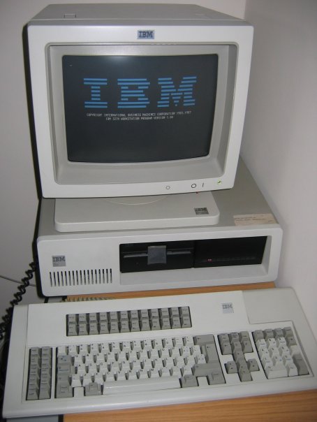
The IBM 5271 can be briefly described as a cross between an XT (model 5160) and a 3270 terminal. Indeed, the 5271 is also known as a "3270 PC".
The case, motherboard, hard and floppy drives, and power supply are all identical (or very similar) to the XT. A specialised keyboard and display (both of which closely resemble the ones used by the IBM 3179 terminal) replace the XT equivalents. To support these, some or all of the following cards will be present:
- Keyboard controller. This also contains the BIOS for all the special cards; so the video cards, for example, won't work without it.
- Video card. I don't think it's got a name, other than "3270 PC Display Adapter" - which, even abbreviated to 3270PCDA, is a bit of a mouthful.
- Host Connect card. Used to connect to the mainframe. The connector is BNC (like 10base2 Ethernet) but isn't Ethernet.
- One or two additional graphics cards (see below).
With all these cards in the machine, that can leave as few as three available ISA slots for the necessities such as hard/floppy drive controllers or extra RAM.
It is possible to convert a 5271 to a normal XT, by removing the specialised display and keyboard cards, and adding a normal display card.
Keyboard
Instead of a normal keyboard, the 5271 uses a 122-key keyboard with 24 function keys and various other 3270-specific keys. The keyboard plugs into a dongle, which in turn connects both to the keyboard socket and to the keyboard controller card.
The 5271 will work with a standard XT keyboard, but displays error 302 when booting; you have to press F1 to continue.
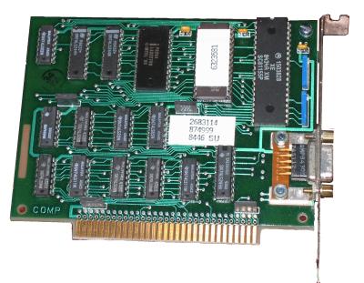
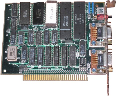
The manual describes two different models of keyboard controller: one with an NMI button and serial port (herein described as the 'complicated' controller), and one without (herein described as the 'simple' controller). Both are illustrated. The manual also says that only the 'complicated' controller supports the use of the 3270 cursor keys in PC programs. Each controller has its own ROM (part no. 6323581 for the 'simple' controller and 6323582 for the 'complicated' one).
Common to both types of controller is the custom chip that handles keyboard signals: it appears to have the IBM part number 1503828, and the Motorola part number SC81155P. Possibly it's a microcontroller, but I don't know what type or (if it is a microcontroller) whether the contents can be read without decapping.
The dongle
The dongle (or, as the Guide to Operations calls it, the keyboard adapter cable) is used to connect the keyboard to the keyboard card and the keyboard card to the PC's normal keyboard socket. As far as I can tell, it contains no electronics of its own; it's just there to split the DE9 socket on the card into a couple of 5-pin DIN connectors.
When I bought my 5271, it was missing its proper dongle, but after copious experimentation I was able to work out the pinout of the socket on the card, and thence a suitable wiring diagram for the dongle. The pinout is:
- XT clock
- XT data
- Key (no pin)
- AT data
- AT clock
- +5v
- Leave disconnected
- Ground
- Ground
To make the substitute dongle, pins 1, 2 and 9 should be connected to the matching pins on the motherboard keyboard connector, and pins 4, 5, 6 and 9 to a 5-pin DIN socket for the terminal keyboard.
(Pins 8 and 9 are both Ground, so it may make more sense to connect Ground on the XT keyboard plug to pin 8 rather than 9).
Since the signals are compatible, it would also be possible to construct a dongle that had a PS/2 socket, or a 5-pin AT socket, instead of a 5-pin terminal socket.
Disclaimer: While I have built a working dongle, it's quite possible that I made a mistake when transcribing the diagram afterwards or numbering the pins. It's a good idea to double-check your wiring against as many references as you can find before actually plugging the thing in...
On the left: an original IBM Keyboard Adapter Cable. On the right: my homemade version.
![[The two dongles,
pictured]](Images/dongles.jpg)
I/O ports, memory, interrupts
The keyboard appears to use I/O ports 01B0h to 01B7h. It can raise interrupts on IRQ2.
If the 3270 scancode 5 (SysRQ) is received, port 0189h is read. The top bit is flipped and the value written back out again.
Ports include:
- 01B0h
- Send keyboard controller command. This appears to be a bitmap,
since all the commands are powers of 2. They include:
- 00h
- Normal operation. After this command, the keyboard status can be read from port 01B2h.
- 02h
- Reset keyboard?
- 08h
- Set XT keyboard clock. When the firmware simulates an XT keypress, it writes the scancode to port 01B1h and then sends 08h followed by 00h to this port.
- 10h
- Send a command to the keyboard (cf writing to port 60h
on an AT-class machine). Command bytes are written to
port 01B1h; then 10h is sent to port 01B0h, and the
keyboard status is read up to 80 times until bit 5
goes high. If bit 5 doesn't go high, keyboard
initialisation is deemed to have failed.
Commands sent during initialisation are:
- F5h
- Set defaults and disable keyboard.
- FCh
- Set some keys to generate break codes. This is done for keys 9, 77h, 7Eh, 65h (CTRL, NumLock, ScrollLock and Insert).
- FAh
- Set some keys to repeat (and only generate make codes). Corresponds to command FBh on a PS/2 keyboard, and is followed by a list of keycodes. The keys it is applied to are the numeric keypad keys, the function keys, and DEL.
- F4h
- Enable keyboard.
- 20h
- Read scancode from keyboard. The scancode can then be read from port 01B2h.
- 40h
- Used in initialisation. 24h is written to the XT scancode port (01B1h). Then the keyboard status is read until bits 6 and 7 go high, which appears to be when a scancode can be read.
- 80h
- Used to acknowledge a keystroke? In the IRQ2 handler, the keyboard status is read. If the low bit is 1, then 80h is written to port 01B0h, followed by 0.
- 01B1h
- Output XT scancodes to this port to send them into the normal keyboard connector. After sending a scancode, send 08h and then 00h to port 01B0h.
- 01B2h
- Data register. Value read depends on last value written to port 01B0h.
- 01B4h-01B7h
- The registers belonging to the 8254 timer on this board.
They get initialised to preset values at startup, and are not
subsequently changed.
Counter 0 generates a square wave with period 4 (possibly a basis for the keyboard clock signals, or perhaps a clock for the microcontroller itself); counters 1 and 2 are set up in software triggered mode with time values of 0DF8h.
The following variables are used in the BIOS data segment:
- 0040:0018
- Bit 0 is 1 if the standard keymap is in use, 0 if a custom keymap has been loaded by INT 52h. It's possible to load two custom keymaps by loading the first, setting this bit, and then loading the second. Note that on AT and later computers, this bit is set if the left ALT key is down.
- 0040:00D2 ('simple' controller only)
- Segment of current scancode translation table. The 'complicated' controller stores this at C040:0110.
- 0040:00D4 ('simple' controller only)
- Segment of alternative scancode translation table. Loading a custom map with INT 52h sets this to the previous default table. Using CTRL+ALT+F1 or CTRL+ALT+F2 to select keymaps swaps the two table pointers over if necessary. The 'complicated' controller stores this at C040:0112.
- 0040:00D6 ('simple' controller only)
- Last translated (XT) scancode. The 'complicated' controller stores this at C040:0114.
- 0040:00EC ('simple' controller only)
- Last 3270 scancode received. The 'complicated' controller stores this at C040:0116.
- 0040:00EF
- Keyboard POST status.
Scancode translation
The keyboard, and its scancodes, now have their own page.Display
The Video Card(s)
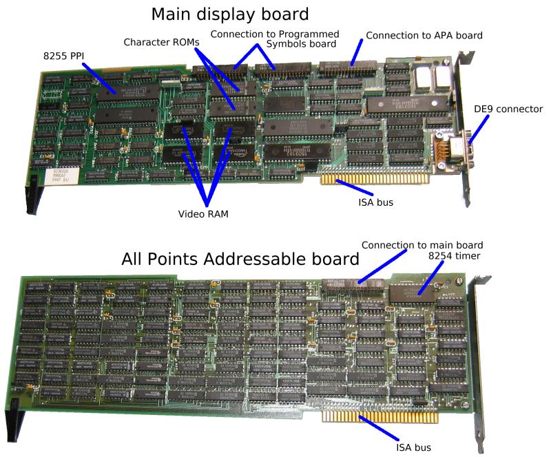
The 5271 video hardware is composed of between one and three full-length ISA cards. If multiple cards are present, they are connected together using rigid connectors.
The three cards are:
- Main card
- Implements 25x80 text mode, and provides video output.
- All Points Addressable option
- Implements CGA graphics modes, plus two modes unique to the 5271.
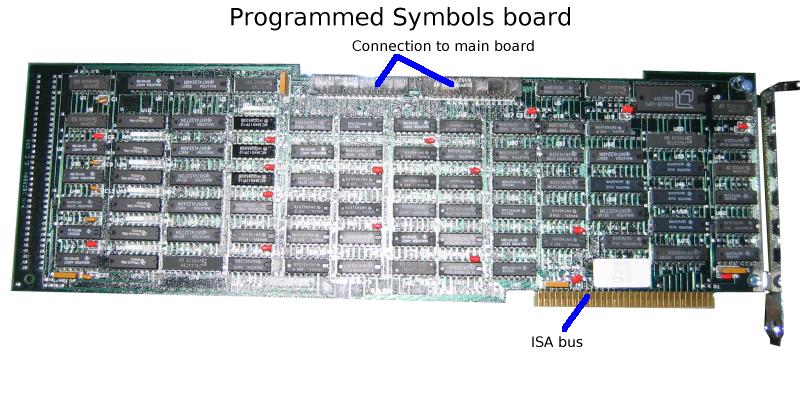
- Programmed Symbols option
- Allows a user-defined character set to be loaded (only used by 3270 terminal emulator software).
The video switches on the motherboard need to be configured as EGA/VGA rather than MDA or CGA. Depending on what hardware is present, the video BIOS will adjust the settings to behave as MDA or CGA. For some reason the video BIOS is (a) located in the ROM on the keyboard controller card; and (b) mapped into memory in two different places.
The 'simple' keyboard controller maps its onboard ROM into memory in two places:
C0000-C07FF: The first 2048 bytes of the ROM: Video self-test
CA000-CA9FF: The remainder of the ROM: Mode changes, the display
            configuration table, and the keyboard.
The 'complicated' controller does something more like this:
C0000-C01FF: The first 512 bytes of the ROM: Self-test of ROM checksum and
            the 512 bytes of RAM.
C0400-C05FF: RAM, used to hold controller state.
CA000-CA3FF: The last 1k of the ROM: the code that has to stay paged at
            all times. Interrupt handlers, helper routines.
CB000-CBBFF: Bank-switching window in which any part of the ROM can be mapped,
            based on the value written to port 12D8h.
The video card behaves rather like a 3270 terminal screen "in front of" a CGA (or MDA) screen. At startup, the 3270 screen is transparent and can't be seen; a terminal emulator program would make it visible.
I don't have a complete pinout for the monitor socket. It's DE9, with at least the following pin assignments:
Pin 3: No connection
Pins 6,7,8: On a colour monitor these are the three colour signals; I'm
            not sure what order they're in.
            On a mono monitor, pin 6 is intensity (probably blue),
            pin 7 is video (probably red), and pin 8 is horizontal
            sync.
Pin 9:      On a mono monitor, pin 9 is vertical sync.
Memory and I/O ports
A0000-A1FFF: 3270 framebuffer
From 0A0000h to 0A1FFFh is the 3270's frame buffer. This appears to have 4 bytes per character cell:
- Byte 0: Character. 0FFh for 'transparent' cell, so the CGA or MDA screen shows through. The other values correspond to characters (not ASCII and not EBCDIC; this is the 3270 internal character set).
- Byte 1: Attribute. Bits 0-2 are background, bits 3-5 foreground. On a mono display, bits 0-4 are ignored and bits 5-7 give attribute (0=normal 1=bright 2=blink 3=bright blink 4=inverse 5=bright inverse 6=underline 7=bright underline).
- Byte 2: If the Programmed Symbols board is not present, this byte cannot be written, and when read is either 0FFh or 0FEh. If the board is present, then the bottom 3 bits select the symbol set to use; 0 for the ROM font, 1-7 for the seven RAM fonts.
- Byte 3: Cannot be written; when read, it is always 0FFh or 0FEh.
AE000-AFFFF: Programmed symbols memory
If bit 3 of port 0188h is set, the initialisation code will test 8k of memory from AE000h to AFFFFh. This holds the RAM font for programmed symbols (see above). The shape data for each character is 16 little-endian words long, with bits 15-7 of the word giving the character shape; bits 6-0 are always zero and cannot be written. The PSS board can hold up to 7 fonts (according to its packaging); port 0195h is used to select which one is visible here.
B0000-B7FFF: MDA framebuffer
This is actually mapped to the same memory as the CGA framebuffer; changes to one will affect the other. The buffer is 4k in size, so it repeats at B1000h, B2000h and so on.
B8000-BFFFF: CGA and APA memory
The main video card actually only has 8k of memory on it - 4k for the 3270 display, and 4k for the MDA/CGA display. So the CGA display RAM repeats at B9000h, BA000h etc (in text modes; the APA board takes over in graphics modes). This means that applications that try to use multiple CGA pages won't get on too well.
If bit 2 of port 0188h is set, the initialisation code will test 32k of memory from 0B8000h to 0BFFFFh. Otherwise it just tests from 0B8000h to 0BBFFFh.
I/O Ports
The I/O ports used by the video card include:
0180h: Writes to this port seem to be used to provide extra parameters
       after a write to port 0181h.
0181h: The diagnostic diskette calls this the command register. Appears to
       be used for a variety of purposes. Values written include:
        00h: Sent at start of initialisation sequence (4 times)
	16h: Set cursor shape. The shape is written to port 0180h; the low
	     nibble is the bottom cursor row, and the high nibble is the top
	     row. Shapes used by the BIOS are 0Dh (block), 0DDh (line) and
	     0FDh (none) but others work as well.
        17h: Used in initialisation sequence; followed by OUT 0180h, 0ACh.
        1Ah: Used in initialisation sequence.
        2Ch: Sent at start of initialisation sequence, after four zero bytes.
             Followed by 11 writes to port 0180h:
                Mono:   68 18 28 40 98 4F DD 8C 00 F0 FF
                Colour: 68 1E 21 07 98 4F DD 8C 00 F0 FF
             Also sent during self-test, but not followed by any bytes.
        2Dh: Select 640x200 graphics mode.
        30h: Select 320x200 graphics mode.
	31h: Select 80x25 text mode.
        3Dh: Used in initialisation sequence.

0182h: Described by the diagnostic diskette as "Start screen address low"
       (all 8 bits are tested)
0183h: Described by the diagnostic diskette as "Start screen address high"
       (bottom 6 bits are tested)
0184h: Real cursor location low (the diagnostic diskette tests all 8 bits)
0185h: Real cursor location high (the diagnostic diskette tests bottom 6 bits)

0188h: Read-only register: Hardware status.
       Bit 7: Vertical retrace?
       Bit 6: Diagnostic readback, red. See 0189h below.
       Bit 5: Diagnostic readback, blue.
       Bit 4: Diagnostic readback, green.
       Bit 3: Set if Programmed Symbols board is present.
       Bit 2: Set if All Points Addressable board is present.
       Bit 1: Set if a monitor is present.
       Bit 0: Monitor type - 1=5272 colour, 0=MDA mono.

0189h: A read/write register. The self-test checks this by storing 0FFh and 0
      in it, and checking that it can read back both values.
       In normal use this register holds either 0C0h or 040h. The
      other value that it gets set to is 20h, which is used during
      the self-test:
      * Write 20h to port 0189h.
      * Wait briefly; then check that specified bits of port 0188h are 0.
      * Write a word value to an address.
      * Wait briefly; then check that specified bits of port 0188h are 1.
      * Write 0C0h to port 0189h.

       My guess as to what is happening: Once 20h is written to port 0189h,
      the three diagnostic bits go high - and stay high - if anything,
      including the cursor, is drawn in the colour in question. So the test
      first checks that blank video RAM causes nothing to be drawn, and then
      that putting values there does cause something to be drawn.

       If the system has a mono monitor, only the 'red' and 'blue' output
      lines appear to be tested.


018Ah:   Used by the diagnostic diskette to detect 3270PC hardware; it writes
       0 to this port and checks that the value returned is 0.

018Bh:   Written by the diagnostic diskette while testing port 0181h.

018Ch:   Interrupt/Control register. Set bit 6 of this port to enable
       interrupts on IRQ2, triggered when a value is written to an emulated
       CGA register. Other bits are always written as 0.
	 The diagnostic diskette tests bits 6 and 0 of this port.

         On read, bit 4 is set if interrupt was triggered by a write to the CGA
       mode control register (port 03D8h); bit 5 if it was triggered by a
       write to the CGA cursor position (6845 registers 0Eh/0Fh) or cursor
       size (registers 0Ah/0Bh).

0190h: Written to by diagnostic diskette, when reinitialising the adapter.
0191h: Written to by diagnostic diskette, when reinitialising the adapter.
0193h: Written to by diagnostic diskette, when reinitialising the adapter.

0195h: Used by PSS board; the diagnostic diskette calls this the PS mask
       register. Bits 0-2 appear to be used to select different banks of
       memory into the character set memory window at 0AE000h.

0196h-019Bh: These registers appear to refer to the All Points Addressable
	     board, and are used to select the extra modes.
             Mode select for 720x350 or 360x350 mode is:

                 OUT 0196, 8
                 OUT 0197, 7Fh
                 OUT 0198, 82h
                 OUT 0198, 3Dh
                 OUT 019A, 2Ch

             For all other modes (text and CGA-compatible graphics), it is:

                 OUT 0196, 0
                 OUT 0197, BFh
                 OUT 0198, 7Ah
                 OUT 0198, 0Ch
                 OUT 019A, 27h

            The initialisation code sends:

                 OUT 0197, 0BFh
                 OUT 0196, 07h
                 OUT 019B, 3Ah
                 OUT 0198, 7Ah
                 OUT 0198, 0Ch
                 OUT 019B, 5Ah
                 OUT 0199, 2Ch
                 OUT 019B, 9Ah
                 OUT 019A, 27h

0197h: When read by the APA self-test, bit 7 must be 0.
       The diagnostic diskette does a more thorough test, writing a 1 to bits
       0-3 in turn, and checking that reads then have bits 0-3 and 7 as 0.

03B4h/03B5h: At least some of the emulated CRTC. The IRQ2 handler reads
      registers 0Eh/0Fh (cursor location) and 0Ah/0Bh (cursor size); on a
      real MDA/CGA, the latter two cannot be read.

03D8h: CGA mode control register. Read/Write in the 3270 PC, because at least
      some CGA emulation is done by the firmware.

12D8h: Used by the 'complicated' keyboard controller card. It appears to set
      which range of the ROM is visible in a memory window from 0CB000h to
      0CBBFFh.
The Monitor
The monitor (model 5272) is bigger than a normal CGA or MDA monitor, and has a swivelling/tilting stand. It is capable of Hercules resolution (720x350) in 7 colours plus black.
A standard MDA monitor can also be used on a 5271. The graphics card detects whether the monitor is colour or mono, and restricts the available video modes accordingly.
The Fonts
The font used in the 5271 uses a 9x14 character cell, the same as the MDA. However the font has been changed from serif to sans-serif, and looks markedly better as a result. In addition, other characters than those in the range 192-223 make use of the 9th pixel column - for instance, the 'q' does.
| IBM 5271 font | IBM MDA font |
|---|---|
![[3270 font]](Images/5271font.png) |
![[MDA font]](Images/mda9.png) |
| The font used for the 3270 terminal framebuffer at 0A0000h uses a 3270 native encoding, which is similar to the "3270 CG" encoding desribed at x3270.bgp.nu, but diverges quite a bit in the last 64 characters. | |
![[3270 terminal font]](Images/5271term.png) | |
The fonts are stored in two 8k ROMs on the display board. One ROM holds the left-hand 8 pixels of each character; the other just holds the ninth pixel.
Colours
In text mode, the 5271 behaves something like a CGA. However, there is no high intensity; 'high intensity' and 'standard' colours look exactly the same. The actual colours look quite different, too.
The following palette values are approximate. The 'normal' ones come from Linux DOSEMU; the '5271' ones from putting a VGA beside the 5271, and fiddling with the VGA palette until the two displays looked similar.
| Colour | IBM 5271 colour | Normal colour |
|---|---|---|
| 0 | #000000 | #000000 |
| 1 | #6080A8 | #0000a8 |
| 2 | #008000 | #00a800 |
| 3 | #60C0A8 | #00a8a8 |
| 4 | #A83000 | #a80000 |
| 5 | #C06080 | #a800a8 |
| 6 | #A08000 | #a85400 |
| 7 | #A0A080 | #a8a8a8 |
The table suggests that the 5271 uses 4 possible levels for each of the three primary colours (roughly, #30, #80, #A0 and #C0). I suspect that these colours are generated in the monitor, with the host PC sending simple on/off levels of Red/Green/Blue.
CGA Emulation and BIOS
Starting at the hardware level: The hardware of the CGA controller is not emulated completely, only enough to support a standard CGA BIOS. The CGA mode control register at 03D8h differs in the following respects:
- The register is read/write, not write-only.
- In text mode, bits 0 (40x25 mode) and 3 (enable/disable display) are ignored completely. Attempts to select a 40x25 mode will be caught by the IRQ2 handler and converted to the corresponding 80x25 mode.
- In graphics modes, changing any bit of this register (except bit 1) will cause the video RAM to be cleared (by the IRQ2 handler). This means that you can't switch between the Red/Cyan/White CGA colour scheme and the other two (Red/Green/Yellow or Magenta/Cyan/White) without a full mode change.
In addition, most of the 6845 CRTC is not emulated; so it is not possible to select the 160x100 "graphics" mode by starting in 24x80 and reprogramming the CRTC.
Although the 5271's graphics card provides its own video BIOS, this does not replace the standard ROM BIOS. The ROM is still used for nearly all functions, the exceptions being function 00h (set mode) and 30h (locate configuration table).
- Function 00h: Set mode
- This does a little extra hardware setup, stores the correct aspect ratio for the selected mode, and then jumps to the ROM BIOS routine. It also supports two extra modes, numbers 30h (720x350 mono graphics) and 31h (360x350 4-colour graphics, using CGA palette).
- Function 30h (CX = 0): Return 3270 PC configuration table
The 6323581 ROM does not check CX. The 6323582 ROM requires CL to be zero, but does not care about CH.
The table returned (CX:DX points to it) is similar to that described in the Interrupt List, but it is at most 6 bytes long, and possibly as few as two:
00h: Aspect ratio X 01h: Aspect ratio Y 02h: Monitor type (0 => MDA or 5272). 03h: Always 0 04h: Video adaptor type (0 => standard 5271, 1 => XGA, 2 => G/GX). 05h: Always 0- Function 30h (CL = 01h)
- Present in the 6323582 ROM only. CH is a (translated) code passed from the keyboard table. CH=0D9h is treated as SysRQ: if ALT is pressed, toggles the top bit of port 0189h, else beep. CH=0FDh always beeps; other values of CH do nothing.
- Function 30h (CL > 1)
- In the 6323582 ROM, calling this function with CL=2 or higher will return leaving CX unchanged and Carry clear.
The two extra graphics modes have a very simple memory layout - simply 350 lines of 90 bytes each, with no interleaving or funny tricks.
The following addresses in the BIOS data segment are used by the 5271 graphics card:
0040:00C8: Aspect ratio X (start of 3270PC configuration table)
0040:00C9: Aspect ratio Y
0040:00D8: BIOS INT 10h handler address.
0040:00EE: Result of self-test (bitmap). 0 if all tests passed; bits set
           if one or more tests failed.
Error codes
- 3201
- Graphics card fault
- 3202
- Programmed Symbols card fault
- 3203
- All Points Addressable card fault
Host Connect Card
There are two types of card supported by IBM's diagnostic program - an "older model long card adapter", and a newer one. The 5271's ROM only detects the older model; this has a 4k buffer at 0CE000h and uses I/O ports from 2D0h to 2D6h. The newer version adds a port at 2D7h (which seems to be used to set the base address of the buffer), increases the size of the buffer, and makes the I/O port base configurable (using switches on the card). A BIOS upgrade to support the new (shorter) cards may have existed.
Error codes
- 2801
- Host Connect card initialisation failed
Related PCs
The 5271 was the first in a line of PCs with hardware support for 3270 terminal emulation. Information about later such PCs is extremely sketchy; but they include:
- The 3270 PC/G and 3270 PC/GX. These added more sophisticated graphics capabilities and mouse support. A different monitor (model 5279 or 5379) is used. According to this USENET thread, the 5279 monitor has a separate tilt/swivel base (5278) packed with circuitry and connected by a connector that's "at least 75 way". Similarly the 5379 (a 19" monitor) uses a 5378 converter box.
- The 3270 AT, 3270 AT/G and 3270 AT/GX - the same sort of specialist cards, but hosted in an AT rather than an XT.
The Interrupt List gives the following display-card-and-monitor combinations:
| Number | Monitor type | Possible models |
|---|---|---|
| 0 | 5151 (mono) or 5272 (colour) | Original 3270 PC or 3270 AT |
| 1 | 3295 plasma display | A large plasma display that could show one, two or four 3270 sessions. |
| 2 | 5151 or 5272 with XGA | Unknown |
| 3 | 5279 with PC/G adaptor | 3270 PC/G or 3270 AT/G |
| 4 | 5379-C01 with PC/GX adaptor | 3270 PC/GX or 3270 AT/GX. Possibly C stands for Colour and M stands for Mono. |
| 5 | 5379-M01 with PC/GX adaptor | 3270 PC/GX or 3270 AT/GX. |
The reference to XGA may be incorrect; in the Interrupt List, it is marked "(???)". XGA is a VGA-compatible standard introduced in 1990, and I can't see it being compatible with MDA (or 5272) monitors, as the list appears to imply.
By the time of the PS/2 era, 102-key keyboards and VGA graphics meant that there was no need for specialised hardware, and later 3270 emulation appears to have been done with just software and a Host Connect card.
Web Links
Other 3270 PC sites
- nothingtodo.org has a picture of a 5271 with its proper keyboard.
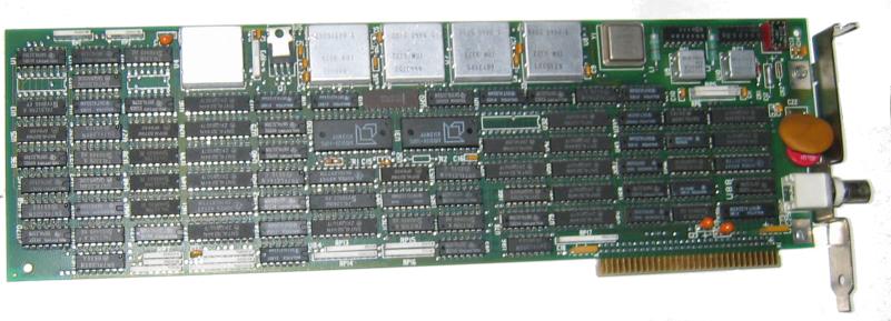
- yesterpc.com has a large number of pictures of the AT version of the 3270PCDA. This differs in various respects from mine; for example, the video BIOS appears to be in a separate chip on the All Points Addressable board rather than being part of the keyboard controller, and both the APA and Programmed Symbols boards are of a shape to fit in a 16-bit ISA slot.
Diagnostics
- Version 2.25 of the XT diagnostic floppy can be downloaded from this archive of IBM reference diskettes. The file in question is XTDGS225.DSK, and you'll also need LOADDSKF.EXE to unpack it.
- From IBM's own site: Diagnostics for the Host Connect card.
Software
- If you use GEM, there is a driver for the 720x350 mono mode, which you can find on the Video Drivers list.
- I have patched Digital Research LOGO to support the 720x350 and 360x350 video modes. This is a CP/M-86 program, so you will need to get hold of Personal CP/M-86 from http://www.cpm.z80.de/binary.html to use it.
The hardware in other systems
Recently the motherboard in my 5271 failed with a blown capacitor, and while I had the PC dismantled pending repairs I experimented with putting the video card in a couple of other XTs to see what would happen. After a bit of fiddling, I was able to get it to work on both systems I tried: a Sinclair PC200, and an Amstrad PC3086. Based on this small sample size, here is my advice for using 5271 hardware on other systems:
- If your XT has any sort of built-in video subsystem, it must be disabled.
- The video cards will only fit in full-length 8-bit ISA slots. I haven't experimented with AT motherboards, but even for a simple test you'd need one with an 8-bit ISA slot. For the full trio of video cards you need three adjacent 8-bit slots at the correct spacing.
- The minimum requirement is two slots, one full-length; the full-length slot for the video card, and the other one for the keyboard controller with the ROM.
- The maximum requirement is five slots - the above cards plus the All Points Addressable, Programmed Symbols and Host Connect boards.
John Elliott 13 March 2010