IDEALISED TERMINAL TO TERMINAL CONNECTION
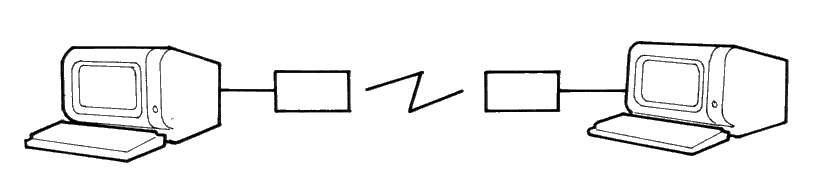
Figure 1.
| Section 3 | Site Index | Book Index |
The MS-DOS operating system allows for a number of installation specific configuration options during the system startup progress through the use of a file called CONFIG.SYS when it is found in the root directory of the startup disk. These configuration options include the following commands:
The CONFIG.SYS can be created with any text editor and the simple screen editor RPED is ideal for this purpose.
This command enables the MS-DOS extended break checking to be either set or reset. Normally, MS-DOS checks to see if [CTRL] [C] has been typed while it is reading from the keyboard, writing to the screen or a printer. Setting Break to 'on' allows [CTRL] [C] checking to be extended to other functions such as disk reads or writes. The syntax of the BREAK command is:
If no field is specified then OFF is assumed (as the default value).
This command allows you to specify the number of buffers that MS-DOS allocates when it starts up. A disk buffer is a block of memory where MS-DOS holds data being read from or written to a disk when the amount of data is not an exact multiple of sector size.
The syntax of the BUFFERS command is:
Where 'n' is a number between 2 and 255. If the BUFFERS command is not used then MS-DOS defaults to 2 buffers. The number of buffers remains in effect after bootstrap until the machine is switched off or bootstrapped again. For best performance for standard applications environments (word processors, spreadsheets, etc.) a buffers allocation between 10 and 20 is recommended. If you tend to use many subdirectories then an allocation upwards to 30 may be better. But since buffers use the system available memory, there may have to be a compromise between memory usage and performance. Buffers allocated beyond 40 serves no useful purpose. Refer to the Users's Manuals for you applications if in douby about required buffers for particular applications programs.
The country command is used to select the country dependent information as shown in appendix 2.
The syntax of the country command is:
The country code is shown in Appendix 2. Note that only the parameters in the table are affected by the country command. Other country dependent factors such as the language links, KEYB, and national variant disks, effect the total country dependent environment.
<code page> is the code page for the country (see appendix 2).
| Filename | is a file containing the country information. If no filename is specified the file COUNTRY.SYS is assumed and it must be available in the root directory. |
Note that the utility, Nlsfunc, can also be used to load country specific information.
This command installs the device driver in the specified pathname to the system list.
The syntax of the DEVICE command is:
The file specified is loaded and given control. The driver may then perform the necessary steps to configure itself and the system for its operation. See the MS-DOS Technical Reference Manual for information on how to create your own device driver.
Your MS-DOS disk (Disk 1) contains two installable device drivers, DRIVER.SYS, and RAMDRIVE.SYS which can be used for variable device configurations.
If you plan to use the ANSI escape sequences described in the PPC Users Manual, you would need to include the following command in your CONFIG.SYS file:
This command causes MS-DOS to replace all keyboard input and screen output support with the ANSI escape sequences. Refer to the PPC User Instructions for ANSI escape sequence reference information.
DRIVER.SYS is an installable device driver that supports external drives. To install DRIVER.SYS, include the following command in your CONFIG.SYS file:
Where:
and optionally:
RAMDRIVE.SYS is an installable device driver which enables the usage of a portion of the computer's memory as though it were a disk drive. This area of memory is referred to as a RAM disk or a virtual disk.
If you have extended memory installed starting at the 1MB boundary or if you have an extended memory which meets the LIM [Lotus(R)/Intel(R)/Microsoft(R)] Expanded Memory Specification, you can use this memory for one or more RAM disks. Otherwise RAMDRIVE.SYS locates RAM drives in low memory.
To install RAMDRIVE.SYS, include the following command in your CONFIG.SYS file:
Where:
There is an additional parameter for this driver which applies to 80286 style CPU architecture with memory above the 1M byte range. This parameter is as follows:
DISPLAY.SYS is an installable device driver which supports code page switching for the console device. A code page is an alternate set of 256 characters which can be used in graphics display modes and with EGA display adapters in text modes.
To install display.sys insert a command line of the following form in your config.sys file:
The CON = parameters are as follows:
Note that there are a set of font selector links within the PPC which are on the lower (main system) board located near the character generator ROM (IC135), and these links select one of four hardware (hwcp) fonts. The two links, labeled LK6 and LK7, are as follows:
| LK7 | LK6 | Selected Character set | hwcp number |
|---|---|---|---|
| Off | Off | English | 437 |
| Off | On | Norwegian | 865 |
| On | Off | Portugese | 860 |
| On | On | Greek |
LK6 is the link closest to pin 28 of the character generator ROM (IC135) and LK7 is located adjacent to LK6 and is parallel to the axis of IC135.
Files EGA.CPI and LCD.CPI are additional code page files for use with the MODE command of the form:
where:
Note that this MODE command should be used in the AUTOEXEC.BAT file.
The DRIVPARM command allows overriding of the device parameters for a specific logical drive.
The syntax is:
Where:
and optionally:
This command allows the overriding of default system parameters for a particular logical drive. This information would be used by the commands which create new diskettes (such as FORMAT and COPY) when writing out the directory and FAT (File Allocation Table) information. For any physical device which is read the information in the FAT ID is used when determining device characteristics for floppy disks, hard disks and tape drives.
If no form factor (/F:) is specified then a value of 2 is assumed (720K, 3.5 inch diskette).
The FCBS command allows you to specify the number of file control blocks available to the system and consequently the number of files which can be opened at any one time.
The syntax of the FCBs is:
Where <x> is the number of FCBs (in the range of 1 to 255) to allocate and <y> is the number of FCBs protected from closure when a program tries to open more than <x> files. The first <y> files opened will be protected. MS-DOS selects the least recently used (non-protected) FCB when it must automatically close a file.
If the FCBS command is not used MS-DOS defaults <x> and <y> to 4 and 0 respectively. It is an error to set <y> greater than <x>
The FILES command specifies the maximum number of file handles that can concurrently be opened. When a program opens a file or a device it is assigned an identifier or "handle" which can be used by that program in referring to the file.
The syntax of the FILES command is:
Where 'n' is the number of handles in the range of 8 to 255. When no FILES command is used MS-DOS assumes a default value of 8. Any value higher than 20 serves no useful function.
The LASTDRIVE command is used to set the maximum drive letter which MS-DOS will accept.
The syntax of the LASTDRIVE command is:
Where 'd' is any letter from A to Z (and is case insensitive). When the drive letter is lower than the actual physical drives then MS-DOS ignores the LASTDRIVE specification and uses the default value which is the letter 'E'.
The SHELL command is used to specify an alternate top-level command processor in place of the standard COMMAND.COM file.
The syntax of the SHELL command is:
This command is used in conjunction with major software packages which furnish their own command processors. The MS-DOS technical manual contains information on developing command processors.
The Stacks command allows you to override the default DOS stack resource parameters. For each hardware interrupt which occurs, MS-DOS allocates a stack to it from the pool of available stacks. When the interrupt process is completed, MS-DOS returns the stack to the available stack pool.
The syntax of the STACKS command is:
If there is no STACKS= command in your CONFIG.SYS file then MS-DOS allocates default stack resources equivalent to the command STACKS=9,128. This however may not be sufficient if you are using multiple interrupting devices (such as LANs, 8087 NDPs, or Hard Disks) and under these circumstances you may experience a number of stack related messages such as "Internal Stack Failure" (most predominantly) or even "Divide Overflow". When messages such as this occur it is advisable to try increasing the stacks, bearing in mind that stacks do use up available system memory in the same way that buffers and FCBs do. The number of stacks allowable is from 8 to 64 and the stack size parameter may vary from 32 to 512 bytes.
| Country | Num | KbC | DcP | AcP | DtF | DtS | TmS | TmF | CSm | CFt | CSd | ThS | DeS | DlS |
|---|---|---|---|---|---|---|---|---|---|---|---|---|---|---|
| Australia | 061 | US | 437 | 850 | 1 | - | : | 0 | $ | 0 | 2 | , | . | , |
| Belgium | 032 | BE | 437 | 850 | 1 | / | : | 1 | BEF | 2 | 2 | , | , | ; |
| Canada (Eng.) | 001 | US | 437 | 850 | 0 | - | : | 0 | $ | 0 | 2 | , | . | , |
| Canada (Fr.) | 002 | CF | 863 | 850 | 2 | - | : | 1 | $ | 3 | 2 | , | , | ; |
| Denmark | 045 | DK | 865 | 850 | 1 | - | . | 1 | kr | 2 | 2 | . | , | ; |
| Finland | 358 | SU | 437 | 850 | 1 | . | . | 1 | mk | 3 | 2 | , | , | ; |
| France | 033 | FR | 437 | 850 | 1 | / | : | 1 | F | 3 | 2 | , | , | ; |
| Germany | 049 | GR | 437 | 850 | 1 | . | . | 1 | DM | 2 | 2 | . | , | ; |
| Italy | 039 | IT | 437 | 850 | 1 | / | : | 1 | L | 0 | 0 | . | , | ; |
| Israel | 972 | -- | 437 | 850 | 1 | / | : | 1 | � | 2 | 2 | , | . | , |
| Latin America | 003 | LA | 437 | 850 | 1 | / | : | 1 | $ | 3 | 2 | , | . | ; |
| Middle East | 785 | -- | 437 | 850 | 1 | / | : | 0 | � | 3 | 3 | . | , | ; |
| Netherlands | 031 | NL | 437 | 850 | 1 | - | : | 1 | ƒ | 2 | 2 | . | , | ; |
| Norway | 047 | NO | 865 | 850 | 1 | / | . | 1 | Kr | 2 | 2 | . | , | ; |
| Portugal | 351 | PO | 860 | 850 | 1 | / | : | 1 | $ | 4 | 2 | . | , | ; |
| Spain | 034 | SP | 437 | 850 | 1 | / | : | 1 | Pt | 3 | 2 | . | , | ; |
| Sweden | 046 | SV | 437 | 850 | 2 | - | . | 1 | SEK | 2 | 2 | . | , | ; |
| Switzerland (Fr.) | 041 | SF | 437 | 850 | 1 | . | . | 1 | Fr | 2 | 2 | , | . | , |
| Switzerland (Ger.) | 041 | SG | 437 | 850 | 1 | . | . | 1 | Fr | 2 | 2 | , | . | , |
| United Kingdom | 044 | UK | 437 | 850 | 1 | - | : | 1 | £ | 0 | 2 | , | . | , |
| United States | 001 | US | 437 | 850 | 0 | - | : | 0 | $ | 0 | 2 | , | . | , |
Table Columns:
| Num | = | Country Number Code. |
| KbC | = | KEYB Code. |
| DcP | = | Default Code Page. |
| AcP | = | Alternate Code Page. |
| DtF | = | Date Format. (0 = U.S. M/D/Y, 1=EURO D/M/Y, 2 = JAPAN Y/M/D) |
| DtS | = | Date Separator. |
| TmS | = | Time Separator. |
| TmF | = | Time Format. (0=12-hour clock, 1=24-hour clock) |
| CSm | = | Currency Symbol. |
| CFt | = | Currency Format. (Bit 0: 0 = Currency symbol Precedes/1=Follows Field, Bits 1 & 2: Number of spaces between Value & Symbol) |
| CSd | = | Number of significant decimal digits in currency. |
| ThS | = | Thousands Separator. |
| DeS | = | Decimal Separator. |
| DlS | = | Data List Separator. |
The items in this table are used in conjunction with the COUNTRY command and the Keyboard Utility (KEYB).
For a complete understanding of the connections required between the RS232C and the outside world, it is important to realize that all devices with a serial interface can be classified as either a modem or as a terminal. Modems are merely a way of extending the length of the connection (often via a terminal wire) between two terminals. Fig 1 (below) shows a simplified, idealised terminal to terminal connection through modems.
IDEALISED TERMINAL TO TERMINAL CONNECTION
Figure 1.
The standard connector used for serial interfaces has 25 pins although only up to seven are required in most cases. When connecting to a modem a 'one-to-one' cable is used, i.e. pin 1 to pin 1, pin 2 to pin 2, ... pin 25 to pin 25. Assuming such cables are in use, data is transferred as follows:
Following the signal path from left to right (in Fig 2), characters from the keyboard are sent as serial data patterns out of pin 2 of the left-hand terminal, to pin 2 of the modem (the connection marked 'transmit data'). The left-hand modem sends the characters via the telephone line, to the right hand modem. The characters are received pin 3 of the right hand modem (the connection marked 'receive data') which sends them to pin 3 of the right-hand terminal. On receipt of the characters, the right-hand terminal displays them on the screen.
Notice how the names of the connections 'transmit data' and 'receive data' are expressed from the view point of the terminals and not the modems.
The data path from left to right just described, is exactly matched by a data path from right to left which uses the same numbered connections, i.e. pin 2 from the right-hand terminal to its modem (transmitting), and then to pin 3 of the left-hand (receiving) modem to the terminal. This arrangement is perfectly symmetrical, and there is no confusion over who is using which pin number and for what direction of data transfer.
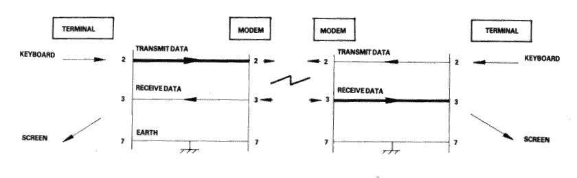
Figure 2.
Problems of definition arise, howeve, when we wish to connect two terminals together locally, without the intervening pair of modems. We cannot connect pin 2 to pin 2 because both keyboard will be transmitting head-on and neither screen is connected to anyone who is sending. The obvious solution is to cross over pins 2 and 3 so that the transmit pin of each terminal is connected to the receive pin of the other. A cable containing such a cross-over connection is known as a 'Null-modem' cable because of the way in which it replaces the pair of back to back modems.
The earth pin (pin 7) is still common to both terminals using this arrangement.
Figure 3
Naturally, the Amstrad PPC with its RS232C interface is considered a terminal, and therefore to connect to a modem (for example, to dial-up a database) requires a simple one-to-one cable.
The Null-modem cable is required for connecting to other terminals. The sort of equipment we mean by terminals is: a second Amstrad computer plus RS232C, a conventional Visual Display Unit (VDU), a printer with a serial interface, or any other serial interface device.
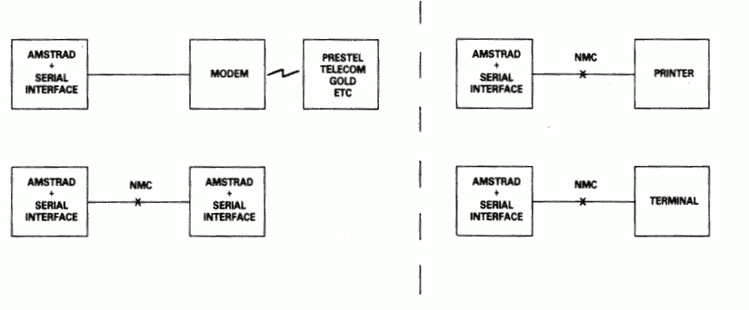
Figure 4
There is a point to be noted here: many manufacturers of devices such as desk-top computers wire up their serial interface (for VDU or a Printer) as if it were a modem, not a terminal. This is in the belief that life will therefore be simpler because VDU's and printers can be connected to that computer with one-to-one cables.
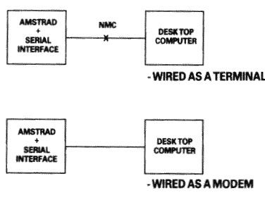
Figure 5.
In a perfect world, it would be possible to identify which serial devices behave like modems and which ones behave like terminals by examining the 'sex' of the 25-way connector - terminals should have a 'male' connector, and modems a 'female' connector. This is not, unfortunately, as reliable a guide as it should be, as many manufacturers of terminals and printers equip them with 'female' connectors, mostly for reasons of electrical safety.
If in doubt, the ultimate test is to examine the user manual and determine the function of PIN 2 - if the description includes the word 'TRANSMIT' then the equipment is wired as a terminal, and if it includes the word 'RECEIVE' then the equipment is wired as a modem.
The simplified connection described so far does not allow any control of the data flow. In practice, we often with the receiving device to have control over the transmitting device, thus preventing the receiving device from being overwhelmed (where it is slower in using the input than the rate at which the input is arriving). In addition, if the transmitting device has reason to mistrust the data which it is sending, there should be some provision for it to disable the receiving device.
In the case of modem to terminal connection; when the terminal is able to transmit it activates pin 4 - the RTS pin (Request To Send). When the modem is ready to receive input it activates pin 5 - the CTS pin (Clear To Send). The terminal will only send when CTS is activated. Thus the modem can control the flow rate using CTS.
When the modem considers that the data which it is about to send is suitable, it activates pin 8 - the DCD pin (Data Carrier Detect). When the terminal is ready to receive input it activates pin 20 - the DTR pin (Data Terminal Ready). The modem will only transmit when DTR is activated. Thus the terminal can control flow rate using DTR.
There are two further signals which must be introduced here. One is on pin 22 - the Ring indicator, which simply allows the modem to tell the terminal that the phone is ringing (at which point software in the terminal might be expected to wake up). The other signal is on pin 6 - DSR (Data Set Ready). This signal is ignored by the receiving side of the RS232C; the modem will activate this signal at much the same time that it activates DCD, and therefore no functionality is lost by ignoring DSR.
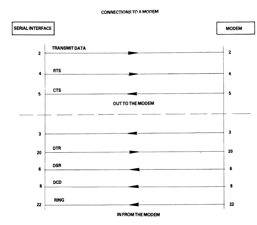
Figure 6.
In the case of terminal-to-terminal conenctions, the Null-modem cable must be used with the additional connections to pins 2, 3, and 7 as already discussed. The full Null-modem cable swaps pins 4 and 8 - the RTS/DCD 'I am happy to send' signals, and pins 20 and 5 - the DTR/CTS 'busy' signals. To be on the safe side, pin 6 (DSR) is connected to pin 8 (DCD) in case that end of the cable is ever connected to a terminal which is fussy and requires DSR as well as DCD.
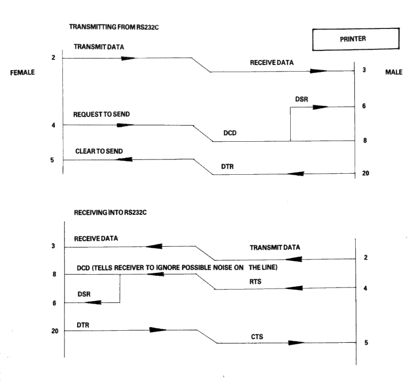
Figure 7.
There is a school of thought which says that a Null-modem cable, unlike the pair of modems it replaces, is ALWAYS 'happy to send'. Therefore it is quite in order to generate DCD (and DSR) permanently. This is achieved by connecting them to the RTS at the same end of the cable, rather than to the RTS at the other end of the cable.
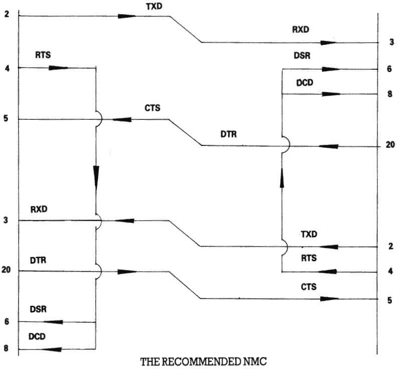
Figure 8.
Finally, if the transmission rate from one of the two terminals is known to be unstoppable (e.g. a person typing at the keyboard), or is so slow and infrequent (e.g. the software handshake characters 'XON, XOFF' sent by the printer) that there is no danger of over-running the receiving end, then it is permissible to permanently enable the transmission by linking pin 5 (CTS) to pin 4 (RTS), i.e. to always send if ready (at the transmitting end of the cable). It may well be facilitated in any case, for the transmitting terminals to ignore the state of CTS under these circumstances.
THE RECOMMEND TERMINAL CABLE
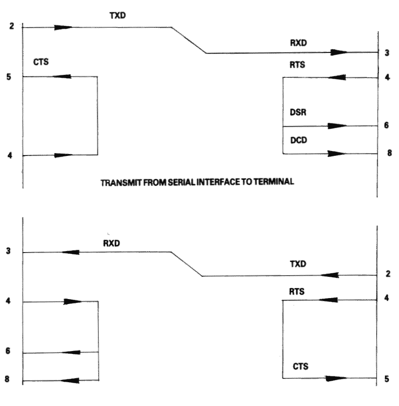
Figure 9
| Line Name | Computer Connector | Printer Connector |
|---|---|---|
| -Strobe | 1 | 1 |
| Data Bit 0 | 2 | 2 |
| Data Bit 1 | 3 | 3 |
| Data Bit 2 | 4 | 4 |
| Data Bit 3 | 5 | 5 |
| Data Bit 4 | 6 | 6 |
| Data Bit 5 | 7 | 7 |
| Data Bit 6 | 8 | 8 |
| Data Bit 7 | 9 | 9 |
| -Ack | 10 | 10 |
| Busy | 11 | 11 |
| PO | 12 | 12 |
| Select Out | 13 | 13 |
| -AutoFd | 14 | 14 |
| -Error | 15 | 32 |
| -Reset | 16 | 31 |
| -Select In | 17 | 36 |
| GND | 18 | 19 |
| GND | 19 | 20 |
| GND | 20 | 21 |
| GND | 21 | 22 |
| GND | 22 | 23 |
| GND | 23 | 24 |
| GND | 24 | 25 |
| GND | 25 | 26 |
| GND | - | 27 |
| GND | - | 28 |
| GND | - | 29 |
| GND | - | 30 |
| GND | - | 33 |
| GND | - | 15 |
| GND | - | 16 |
| GND | - | 17 |
| GND | - | 18 |
| GND | - | 34 |
| GND | - | 35 |
The PPC power usage from the batteries is as follows:
| 1. Power OFF (internal RTC running) | 1mA |
| 2. Power ON and RAM resident process, disk motors off | 620mA |
| 3. Power ON and RAM resident process, disk motors on | 870mA |
It is not recommended that the modem be used with the batteries otherwise the usable 1A rating of the batteries will be exceeded. As the batteries age their voltage output will drop and the current regulator will increase the current demand to maintain the internal electronics board power supply output. This process will foreshorten battery life considerably, as the batteries age.
The PPC power usage from the AC adapter is as follows:
| 1. Power OFF (batteries supplying RTC) | 100mA |
| 2. Power ON and ROM resident process, disk motors off | 740mA |
| 3. Power ON and RAM resident process, disk motors off | 850mA |
| 4. Power ON and RAM resident process, disk motors on | 1100mA |
| 5. Power ON and RAM resident process, modem active | 1220mA |
| 6. Power ON and RAM resident process, modem & disk active | 1470mA |
The power usage during power off condition is due to a bleed resister in the adapter circuit, used to stablize the adapter so that it will not supply open circuit voltage to the computer. The voltage from the AC adapter with just bleed current is approximately 15 volts. The minimum voltage with RAM resident process, modem and disk both active is approximately 13.5 volts.
|
|
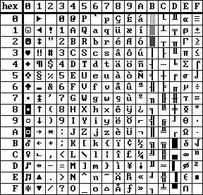
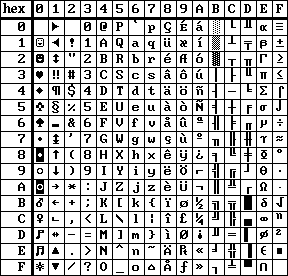
| ENGLISH character set | NORWEGIAN character set |
|
|
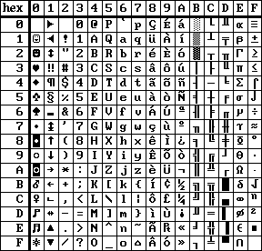
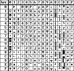
| PORTUGESE character set | GREEK character set |
NOTE: Character sets are selected using the character set selection links described on page 141.
|

|
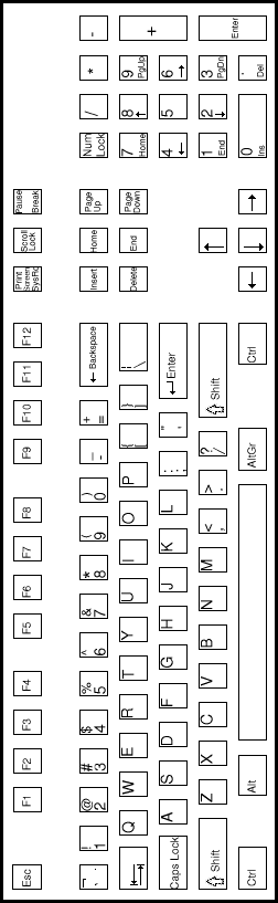
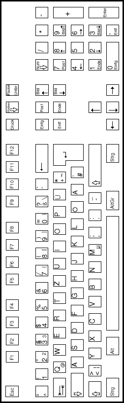
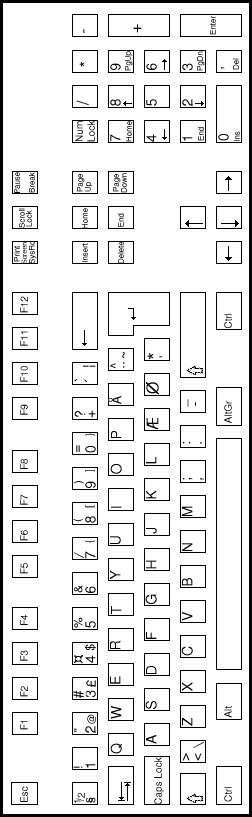
| UK keyboard | USA keyboard |
* keys designated by an asterix are extended keys and give extended key sequences as documented in section 2.3.4.
Note 1: This key, the Print Screen/Sys req key, gives the keycode sequence E0h, 2Ah, E0h, 37h when typed.
Note 2: This key, the Pause/Break key, gives the keycode sequence E1h, 1Dh, 45h when typed.
|
|
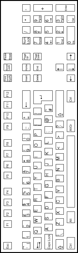
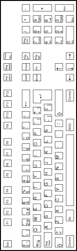
| USA keyboard | UK keyboard |
|
|
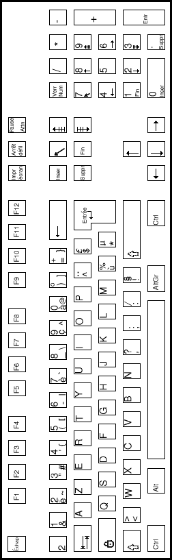
| FRENCH keyboard | GERMAN keyboard |
|
|
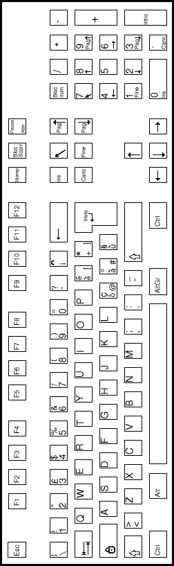
| SPANISH keyboard | ITALIAN keyboard |
|
|
| SWEDISH keyboard | DANISH keyboard |

|

|
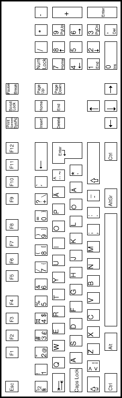
| PORTUGESE keyboard | NORWEGIAN keyboard |
In this appendix you will learn about MS-LINK. It is recommended that you read the entire appendix before you use MS-LINK.
The MS-DOS linker (called MS-LINK) is a program that:
When you write a program, you write it in source code. This source code is passed through a compiler which produces object modules. The object modules must be passed through the link process to produce machine language that the computer can understand directly. This machine language is in the form required for running programs.
You may wish to link (combine) several programs and run them together. Each of your programs may refer to a symbol that is defined in another object module. This reference is called an external reference.
MS-LINK combines several object modules into one relocatable load module, or Run file (called an .EXE or Executable file). As it combines modules, MS-LINK can search several library files for definitions of any external references that are not defined in the object modules.
MS-LINK also produces a List file that shows external references resolved, and it also displays any error messages.
MS-LINK uses available memory as much as possible. When available memory is exhausted, MS-LINK creates a temporary disk file named VM.TMP.
Figure 1 illustrates the various parts of the MS-LINK operation:
![[Figure 1]](http://www.seasip.info/AmstradXT/ppctech/a191.png)
Figure 1. The MS-LINK Operation
Some of the terms used in this appendix are explained below to help you understand how MS-LINK works. Generally, if you are linking object modules compiled from BASIC, Pascal, or a high-level language, you will not need to know these terms. However, if you are writing and compiling programs in assembly language you will need to understand MS-LINK and the definitions of the memory divisions of MS DOS.
In MS DOS, memory can be divided into segments, classes and groups. Figure 2 illustrates these concepts.
![[Figure 1]](http://www.seasip.info/AmstradXT/ppctech/a192.png)
Shaded area = a group (64K bytes addressable)
Figure 3. How Memory Is Divided
Example:
| Segment Number | Name | Class |
|---|---|---|
| 1 | PROG.1 | CODE |
| 2 | PROG.2 | CODE |
| 12 | PROG.3 | DATA |
Note that segments 1, 2 and 12 have different segment names, and may or may not have the same segment class name. Segments 1, 2 and 12 form a group with a group address of the lowest address of segment 1 (ie., the lowest address in memory).
Each segment has a segment name and a class name from the first segment encountered to the last. All segments assigned to the same class are loaded into memory contiguously.
During processing, MS-LINK references segments by their addresses in memory (where they are located). MS-LINK does this by finding groups of segments.
A group is a collection of segments that fit within a 64K byte area of memory. The segments do not need to be contiguous to form a group (see illustration). The address of any group is the lower address of the segments within that group. At link time, MS-LINK analyses the groups, then references the segments by the address in memory fo that group. A program may consist of one or more groups.
If you are writing in assembly language, you may assign the group and class names in your program. In high-level languages (BASIC, COBOL, FORTRAN, Pascal), the naming is done automatically by the compiler.
MS-LINK:
For each type of file, the user may give a three-part file specification. The format for MS-LINK file specifications is the same as that of a disk file:
[d:]<filename>[<.ext>)
where:
If no filename extensions are given in the input (object) file specifications, MS-LINK will recognize the following extensions by default:
MS-Link appends the following default extensions to the output (Run and List) files:
MS-Link uses available memory for the link session. If the files to be linked create an output file that exceeds available memory, MS-LINK will create a temporary file, name it VM.TMP, and put it in the disk in the default drive. If MS-LINK creates VM.TMP, it will display the message:
VM.TMP has been created.
Do not change diskette in drive, <d:>
Once this message has been displayed, you must not remove the disk from the default drive until the link session ends. if the disk is removed, the operation of MS-LINK will be unpredictable, and MS-LINK might display the error message:
Unexpected end of file on VM.TMP
The contents of VM.TMP are written to the Run file. (The name of the file is written at the Run file prompt). VM.TMP is a working file only and is deleted at the end of the linking session.
Do not use VM.TMP as a filename for any file. If you have a file named VM.TMP on the default drive and MS-LINK requires the VM.TMP file, MS-LINK will delete the VM.TMP already on disk and create a new VM.TMP. Thus the contents of the previous VM.TMP file will be lost.
MS-LINK requires two types of input: a command to start MS-LINK and responses to command prompts. In addition, seven switches control MS-LINK features. Usually, you will type all the commands to MS-LINK on the terminal keyboard. As an option, answers to the command prompts and any switches may be contained in a response file. Command characters can be used to assist you while giving commands to MS-LINK.
MS-LINK may be started in any of three ways. The first method is to type the commands in response to individual prompts. In the second method, you type all commands on the line used to start MS-LINK. To start MS-LINK by the third method, you must create a response file that contains all the necessary commands and tell MS-LINK where that file is when you start MS-LINK.
Summary of Methods to start MS-LINK
To start MS-LINK with Method 1, type:
LINK
MS-LINK will be loaded into memory. MS-LINK will then display four text prompts that appear one at a time. You answer the prompts to command MS-LINK to perform specific tasks.
At the end of each line, you may type one or more switches, preceded by the switch character, a forward slash (/)
The command prompts are summarised below and described in more detail in the "Command Prompts" section.
To start MS-LINK with Method 2, type all commands on one line. the entries following LINK are responses to the command prompts. The entry fields for the different prompts must be separated by commas. Use the following syntax:
LINK <object-list>, <runfile>, <listfile>, <lib-list> [/switch...]
where :-
/switch refers to optional switches, which may be placed following any of the response entries (just before any of the commas or after the <lib-list>, as shown.
To select the default for a field, simply type a second comma with no spaces between the two commas.
Example:
LINK FUN+TEXT+TABLE+CARE/P/M+FUNLIST,COBLIB.LIB
This command causes MS-LINK to be loaded, then the object modules FUN.OBJ, TEXT.OBJ, TABLE.OBJ, and CARE.OBJ are loaded. MS-LINK then pauses (as a result of using the /P switch). MS-LINK links the object modules when you press any key, and produces a global symbol map (the /M switch); defaults to FUN.EXE Run file; creates a List file named FUNLIST.MAP; and searches the library file COBLIB.LIB.
To start MS-LINK with Method 3, type:
LINK @<filespec>
where: filespec is the name of a response file. A response file contains answers to MS-LINK prompts (shown in Method 1) and may also contain any of the switches. When naming a response file, the use of filename extensions is optional. Method 3 permits the command that starts MS-LINK to be entered from the keyboard or within a batch file without requiring you to take any further action.
To use this option, you must create a response file containing several lines of text, each of which is the response to an MS-LINK prompt. The response must be in the same order as the MS-LINK prompts discussed in Method 1. If desired, a long response to the Object Modules: or Libraries: prompt may be typed on several lines by using a plus sign (+) to continue the same response onto the next line.
Use switches and command characters in the response file the same way as they are used for responses typed on the terminal keyboard.
When the MS-LINK session begins, each prompt will be displayed in order with the responses from the response file. If the response file does not contain answers for all the prompts, (in the form of filenames, the semicolon character or carriage returns), MS-LINK will display the prompt which does not have a response, then wait for you to type a legal response. When a legal response has been typed, MS-LINK continues the link session.
Example Response File:
FUN TEXT TABLE CARE
/PAUSE/MAP
FUNLIST
COBLIB.LIB
This response file tells MS-LINK to load the four object modules named FUN, TABLE and CARE. MS-LINK pauses before producing a public symbol map to permit you to swap disks (see discussion under /PAUSE in the "Switches" section before using this feature). When you press any key, the output files will be named FUN.EXE and FUNLIST.MAP. MS-LINK will search the library file COBLIB.LIB, and will use the default settings for the switches.
MS-LINK provides three command characters:
Use the plus sign (+) to separate entries and to extend the current line in response to the Object Modules: and Libraries: prompts. (A blank space may be used to separate object modules.) To type a large number of responses (each may be very long), type a plus sign followed by the [RETURN] key at the end of the line to extend it. If the plus sign is the last character typed before pressing the [RETURN] key, MS-LINK will prompt you for more module names. When the prompt 'Object Modules:' or the prompt 'Libraries:' appears again, continue to type responses. When all the modules to be linked and libraries to be searched have been input, be sure the response line ends with the last module name and a [RETURN] and not a plus sign and [RETURN].
Example:
Object Modules [.OBJ]: FUN TEXT TABLE CARE <RETURN>
Object Modules [.OBJ]: FOO+FLIPPFLOP+JUNQUE <RETURN>
Object Modules [.OBJ]: CORSAIR <RETURN>
To select default responses to the remaining prompts, use a single semicolon (;) followed by a [RETURN] at any time after the first prompt (Run file:). This feature saves time and overrides the need to press a series of [RETURN] keys.
Once the semicolon has been typed and entered (by pressing the [RETURN] key), you can no longer respond to any of the prompts for that link session. Therefore, do not use the semicolon to skip some prompts. To skip prompts, use the [RETURN] key.
Example:
Object Modules [.OBJ]: FUN TEXT TABLE CARE [RETURN]
Run Module [FUN.EXE]: ;[RETURN]
No other prompts will appear, and MS-LINK will use the default values (including FUN.MAP for the List file).
MS-LINK asks you for responses to four text prompts. When you have typed a response to a prompt and pressed [RETURN], the next prompt appears. When the last prompt has been answered, MS-LINK begins linking automatically without further command. when the link session is finished, MS-LINK exits to the operating system. When the operating system prompt appears, Ms-LINK has finished successfully. If the link session is unsuccessful, MS-LINK will display the appropriate error message.
MS-LINK prompts you for the names of Object, Run, and List files, and for Libraries. The prompts are listed in order of appearance. The default response is shown in square brackets ([ ]) following the prompt for prompts which can default to preset responses. The object Modules: prompt has no preset filename response and requires you to type a filename.
Type a list of the object modules to be linked. MS-LINK assumes by default that the filename extension is .OBJ. If an object module has any other filename extension, the extension must be given. Otherwise, the extension may be omitted.
Modules must be separated by plus signs (+).
Remember that MS-LINK loads segments into classes in the order encountered. You can use this information to set the order in which the object modules will be read by MS-LINK.
Typing a filename will create a file for storing the Run (executable) file that results from the link session. All Run files receive the filename extension .EXE, even if you specify an extension other than .EXE.
If no response is typed to the 'Run File:' prompt, MS-LINK uses the first filename typed in response to the Object Modules: prompt as the RUN filename.
Example:
Run File [FUN.EXE]: B:PAYROLL/P
This response directs MS-LINK to create the Run file PAYROLL.EXE on drive B:. Also MS-LINK will pause, which allows you to insert a new disk to receive the Run file.
The List file contains an entry for each segment in the input (object) modules. Each entry also shows the addressing in the Run file.
The default response is the Run filename with the default filename extension '.MAP'.
The valid responses are up to eight library filenames or simply a [RETURN] (A [RETURN] means default library search). Library files must have been created by a library utility. In default, MS-LINK will assume that the filename extension is .LIB for library files.
Library filenames must be separated by blank space or plus signs (+).
MS-LINK searches library files in the order listed to resolve external references. When it finds the module that defines the external symbol, MS-LINK processes that module as another object module.
If MS-LINK cannot find a library file on the disk drives, it will display the message:
Cannot find library <library-name> Type new drive letter:
Press the letter for the drive designation (for example, B).
The seven MS-LINK switches control various MS-LINK functions. Switches must be typed at the end of a prompt response, regardless of which method is used to start MS-LINK. Switches may be grouped at the end of any response, or may be scattered at the end of several. If more than one switch is typed at the end of one response, each switch must be preceded by a forward slash (/).
All switches may be abbreviated. The only restriction is that an abbreviation must be sequential from the first letter through the last typed and no gaps or transpositions are allowed. Some legal and illegal abbreviations for the /DSALLOCATE switch are as follows:
| Legal | Illegal |
|---|---|
| /D | /DSL |
| /DS | /DAL |
| /DSA | /DLC |
| /DSALLOCA | /DSALLOCT |
| /DSALLOCATE |
Using the /DSALLOCATE switch tells MS-LINK to load all data at the high end of the Data Segment. Otherwise MS-LINK loads all data at the low end of the Data Segment. At run time, the DS pointer is set to the lowest possible address to allow the entire DS segment to be used. Use of the /DSALLOCATE switch in combination with the default load low (that is, the /HIGH switch is not used) premits the user application to dynamically allocate any available memory below the area specifically allocated with DGroup, yet to remain accessible by the same DS pointer. This dynamic allocation is needed for Pascal and FOTRAN programs.
Note:
Your application program may dynamically allocate up to 64K bytes (or the
actual amount of memory available) less the amount allocated within DGroup.
Use of the /High switch causes MS-LINK to place the Run file as high as possible in memory. Otherwise, MS-Link places the Run file as low as possible.
IMPORTANT
Do not use the /High switch with Pascal or FORTRAN programs.
The /LINENUMBERS switch tells MS-LINK to include in the List file the line numbers and addresses of the source statements in the input modules. Otherwise, line numbers are not included in the List file.
Note:
Not all compilers produce object modules that contain line number information. In these cases, of course, MS-LINK cannot include line numbers.
/Map directs MS-LINK to list all public (global) symbols defined in the input modules. If /MAP is not given, MS-LINK will list only errors (including undefined globals).
The symbols are listed alphabetically. For each symbol, MS-LINK lists its value and its segment:offset location in the Run file. The symbols are listed at the end of the List file.
The /PAUSE switch causes MS-LINK to pause in the link session when the switch is encountered. Normally, MS-LINK performs the linking session from beginning to end without stopping. This switch allows the user to swap the disks before MS-LINK outputs the Run (.EXE) file.
When MS-LINK encounters the /PAUSE switch, it displays the message:
About to generate .EXE file Change disks <hit any key>
MS-LINK resumes processing when the user presses any key.
CAUTION
Do not remove the disk which will receive the List file, or the disk used for the VM.TMP file, if one has been created.
Number represents any positive numeric value (in hexadecimal radix) up to 65536 bytes. If a value from 1 to 511 is typed, MS-LINK will use 512. If the /STACK switch is not used for a link session, MS-LINK will calculate the necessary stack size automatically.
All compilers and assemblers should provide information in the object modules that allow the linkter to compute the required stack size.
At least one object (input) module must contain a stack allocation statement. If not, MS-LINK will display the following error message:
WARNING: NO STACK SEGMENT
This sample shows you the type of information that is displayed during an MS-LINK session.
In response to the MS-DOS prompt, type:
LINK
The system displayes the following messages and prompts:
MICROSOFT Object Linker V.2.00 (C) Copyright 1982 by Microsoft Inc.
Object Modules [.OBJ]: IO SYSINT <RETURN>
Run File [IO.EXE]: <RETURN> list file [NUL.MAP]: IO /MAP <RETURN>
Libraries [.LIB]: ;<RETURN>
Notes:
Once MS-LINK locates all libraries, the linker map displays a list of segments in the order of their appearance within the load module. The list might look like this:
	Start	Stop	Length	Name
	00000H	009ECH	09EDh	CODE
	009F0H	01166H	0777H	SYSINTSEG
The information in the Start and Stop columns shows the 20-bit hex address of each segment relative to location zero. Location zero is the beginning of the load module.
The addresses displayed are not the absolute addresses where these segments are loaded. Consult the MS-DOS 2.0 Macro Assembler Manual for information on how to determine where relative zero is actually located, and also on how to determine the absolute address of a segment.
Because the /MAP switch was used, MS-LINK displays the public symbols by name and value. For example:
	ADDRESS		PUBLICS BY NAME

	009F:0012	BUFFERS
	009F:0005	CURRENT_DOS_LOCATION
	009F:0011	DEFAULTDRIVE
	009F:000B	DEVICE_LIST
	009F:0013	FILES
	009F:0009	FINAL_DOS_LOCATION
	009F:000F	MEMORY_SIZE
	009F:0000	SYSINIT

	ADDRESS		PUBLICS BY VALUE

	009F:0000	SYSINIT
	009F:0005	CURRENT_DOS_LOCATION
	009F:0009	FINAL_DOS_LOCATION
	009F:000B	DEVICE_LIST
	009F:000F	MEMORY_SIZE
	009F:0011	DEFAULTDRIVE
	009F:0012	BUFFERS
	009F:0013	FILES
All errors cause the link session to abort. After the cause has been found and corrected, MS-LINK must be re-run. The following messages are displayed by MS-LINK:
When MS-DOS is initially loaded the system commands processor, COMMAND.COM is loaded and becomes the resident command line processor. You can however call the command processor by using, the syntax below:
command [ <drive:> <pathname>] [<cttydev>] [/p] [/c <string>] [/e <environment size>]
This command starts a new command processor (the MS-DOS program that contains all internal commands).
The command processor is loaded into memory in two parts: the transient part and the resident part. Some application programs write over the transient part of COMMAND.COM when they run. When this happens, the resident part of the command processor looks for the COMMAND.COM file on disk so it can reload the transient part.
The <drive:> <pathname> options tell the command processor where to look for the COMMAND.COM file it it needs to reload the transient part into memory.
<cttydev> allows you to specify a different device (such as aux) for input and output. See the Ctty command in this chapter for more information.
The /e switch specifies the environment size in bytes. The size may range between 128 and 32768 bytes. The default value is 128 bytes.
If <environment size> is less than 128 bytes, MS-DOS defaults to 128 bytes and gives the message:
Invalid environment size specified
If <environment size> is greater than 32768 bytes, MS-DOS gives the same message, but defaults to 32768 bytes.
The /p switch tells COMMAND.COM not to exit to any higher level.
The /c switch, if used, should be the last switch in the command. It tells the command processor to execute the command or commands specified by <string> and then return.
Example:
command /c chkdsk b:
This example tells the command processor to:
The Microsoft DEBUG Utility (DEBUG) is a debugging program that provides a controlled testing environment for binary and executable object files. Note that EDLIN is used to alter source files; DEBUG is EDLIN's counterpart for binary files. DEBUG eliminates the need to reassmeble a program to see if a problem has been fixed by a minor change. It allows you to alter the contents of a file or the contents of a CPU register, and then to immediately re-execute a program to check on the validity of the changes.
All DEBUG commands may be aborted at any time by pressing [Control][C]. [Control][S] suspends the display, so that you can read it before the output scrolls away. Entering any key other than [Control][C] or [Control][S] restarts the display. All of these commands are consistent with the control character functions available at the MS-DOS command level.
DEBUG may be started two ways. By the first method, you type all commands in response to the DEBUG prompt (a hyphen). By the second method, you type all commands on the line used to start DEBUG.
Summary of Methods to Start DEBUG
To start DEBUG using method 1, type:
DEBUG
DEBUG responds with the hyphen (-) prompt, signaling that it is ready to accept your commands. Since no filename has been specified, current memory, disk sectors or disk files can be worked on by using other commands.
To start DEBUG using a command line, type:
DEBUG [ <filespec> [ <arglist> ]]
For example, if a <filespec> is specified, then the following is a typical command to start DEBUG:
DEBUG FILE.EXE
DEBUG then loads FILE.EXE into memory starting at 100 hexadecimal in the lowest available segment. The BX:CX registers are loaded with the number of bytes placed into memory.
An <arglist> may be specified if <filespec> is present. The <arglist> is a list of filename parameters and switches that are to be passed to the program <filespec>. Thus, when <filespec> is loaded into memory, it is loaded as if it had been started with the command:
<filespec> <arglist>
Here, <filespec> is the file to be debugged, and the <arglist> is the rest of the command line that is used when <filespec> is invoked and loaded into memory.
Each DEBUG command consists of a single letter followed by one or more parameters. Additionally, the control characters and the special editing functions described in the MS-DOS User's Guide, apply inside DEBUG.
If a syntax error occurs in a DEBUG command, DEBUG reprints the command line and indicates the error with an up-arrow (↑) and the word "error."
For example:
	dcs:100 cs:110
	        ^  Error
Any combination of uppercase and lowercase letters may be used in commands and parameters.
The DEBUG commands are summarized in Table 11.1 and are described in detail, with examples, following the description of command parameters.
Table 11.1 DEBUG Commands
All DEBUG commands accept parameters, except the Quit command. Parameters may be separated by delimiters (spaces or commas), but a delimiter is required only between two consecutive hexadecimal values. Thus, the following commands are equivalent:
| PARAMETER | DEFINITION |
|---|---|
| <drive> | A one-digit hexadecimal value to indicate which drive a file will be loaded from or written to. the valid values are 0-3. These values designate the drives as follows: 0=A:, 1=B:, 2=C:, 3=D:. |
| <byte> | A two-digit hexadecimal value to be placed in or read from an address or reigster. |
| <record> | A 1- to 3-digit hexadecimal value to be used to indicate the logical record number on the disk and the number of disk sectors to be written or loaded. Logical records correspond to sectors. However, their numbering differs since they represent the entire disk space. |
| <value> | A hexadecimal value up to four digits used to serial a port number or the number of times a command should repeat its functions. |
| <address> | A two-part designation consisting of either an alphabetic segment register designation or a four-digit segment address plus an offset value. The segment designation or segment address may be omitted, in which case the default segment is used. DS is the default segment for all commands except G, L, T, U and W, for which the default segment is CS. All numeric values are hexadecimal. For example:
The colon is required between a segment designation (whether numeric or alphabetic) and an offset. |
| <range> | Two <address>es: e.g., <address> <address>; or one <address>, an L, and a <value> e.g. <address> L <value> where: |
| <value> | is the number of lines the command should operate on, and L80 is assumed. The last form cannot be used if another hex value follows the <range>, since the hex value would be interpreted as the second <address> of the <range>. Examples:
The following is illegal:
CS:100 CS:110
       ^ Error
The limit for <range> is 10000 hex. To specify a value of <10000> hex within four digits, type 00 (or 0). |
| <list> | A series of <byte> values or of <string>s. <list> must be the last parameter on the command line. Example: fcs:100 42 45 52 54 41 |
| <string> | Any number of characters enclosed in quote marks. Quote marks must be either single (') or double ("). If the delimiter quote marks must appear within a <string>, the quote marks must be doubled. For example, the following strings are legal:
However, this string is illegal:
Similarly, these strings are legal:
However, this string is illegal:
Note that the double quote marks are not necessary in the following strings:
The ASCII values of the characters in the string are used as a <list> of byte values. |
| NAME | Assemble |
| PURPOSE | Assembles 8086/8087/8088 mnemonics directly into memory. |
| SYNTAX | A[<address>] |
If a syntax error is found, DEBUG responds with
^ Error
and re-displays the current assembly address.
All numeric values are hexadecimal and must be entered as 1-4 characters. Prefix mnemonics must be specified in front of the opcode to which they refer. They may also be entered on a separate line.
The segment override mnemonics are CS:, DS:, ES:, and SS:. The mnemonic for the far return is RETF. String manipulation mnemonics must explicitly state the string size. For example, use MOVSW to move word strings and MOVSB to move byte strings.
The assembler will automatically assemble short, near or far jumps and calls, depending on byte displacement to the destination address. These may be overridden with the NEAR or FAR prefix. For example:
	0100:0500 JMP 502	;a 2-byte short jump
	0100:0502 JMP NEAR 505	;a 3-byte near jump
	0100:0505 JMP FAR 50A	;a 5-byte far jump
The NEAR prefix may be abbreviated to NE, but the FAR prefix cannot be abbreviated.
DEBUG cannot tell whether some operands refer to a word memory location or to a byte memory location. In this case, the data type must be explicitly stated with the prefix "WORD PTR" or "BYTE PTR". Acceptable abbreviations are "WO" and "BY". For example:
	NEG	BYTE PTR [128]
	DEC	WO [SI]
DEBUG also cannot tell whether an operand refers to a memory location or to an immediate operand. DEBUG uses the common convention that operands enclosed in square brackets refer to memory. For example:
	MOV	AX,21	;Load AX with 21H
	MOV	AX,[21]	;Load AX with the
			;contents
			;of memory location 21H
Two popular pseudo-instructions are available with Assemble. The DB opcode will assemble byte values directly into memory. The DW opcode will assemble word values directly into memory. For example:
	DB	1,2,3,4,"THIS IS AN EXAMPLE"
	DB	'THIS IS A QUOTE:"'
	DB	"THIS IS A QUOTE:'"
	DW	1000,2000,3000,"BACH"
Assemble supports all forms of register indirect commands. For example:
	ADD	BX,34[BP+2].[SI-1]
	POP	[BP+DI]
	PUSH	[SI]
All opcode synonyms are also supported. For example:
	LOOPZ	100
	LOOPE	100

	JA	200
	JNBE	200
For 8087 opcodes, the WAIT or FWAIT must be explicitly specified. For example:
FWAIT FADD ST,ST(3)	;This line assembles
			;an FWAIT prefix
LD TBYTE PTR [BX]	;This line does not
| NAME | Compare |
| PURPOSE | Compares the portion of memory specified by <range> to a portion of the same size beginning at <address>. |
| SYNTAX | C<range> <address> |
If the two areas of memory are identical, there is no display and DEBUG returns with the MS-DOS prompt. If there are differences, they are displayed in this format:
<address1> <byte1;> <byte2;> <address2>
For example, The following commands have the same effect:
C100,1FF 300C100 L100 300
- or
Each command compares the block of memory from 100 to 1FFH with the block of memory from 300 to 3FFH.
| NAME | Dump |
| PURPOSE | Displays the contents of the specified region of memory. |
| SYNTAX | D[<range>] |
If a range of addresses is specified, the contents of the range are displayed. If the D command is typed without parameters, 128 bytes are displayed at the first address (DS:100) after the address displayed by the previous Dump command.
The dump is displayed in two portions: a hexadecimal dump (each byte is shown in hexadecimal value) and an ASCII dump (the bytes are shown in ASCII characters). Nonprinting characters are denoted by a period (.) in the ASCII portion of the display. Each display line shows 16 bytes with a hyphen between the eighth and ninth bytes. At times, displays are split in this manual to fit them on the page. Each displayed line begins on a 16-byte boundary.
If you type the command:
dcs:100 10F
DEBUG displays the dump in the following format:
04BA:0100 54 4F 4D 20 53 41 57 59-45 52 24 00 00 09 4E 44 TOM SAWYER$...ND
If you type the following command:
D
The display is formatted as described above. Each line of the display begins with an address, incremented by 16 from the address on the previous line. Each subsequent D (typed without parameters) displays the bytes immediately following those last displayed.
If you type the command:
DCS:100 L20
the display is formatted as described above, but 20H bytes are displayed.
If then you type the command:
DCS:100 115
the display is formatted as described above, but all the bytes in the range of lines from 100H to 115H in the CS segment are displayed.
| NAME | Enter |
| PURPOSE | Enters byte values into memory at the specified <address>. |
| SYNTAX | E<address> [<list>] |
If the optional <list> of values is typed, the replacement of byte values occurs automatically. (If an error occurs, no byte values are changed.)
If the <address> is typed without the optional <list>, DEBUG displays the address and its contents, then repeats the address on the next line and waits for your input. At this point, the Enter command waits for you to perform one of the following actions:
For example, assume that the following command is typed:
ECS:100
DEBUG displays:
04BA:0100 EB .To change this value to 41, type 41 as shown:
04BA:0100 EB.41
To step through the subsequent bytes, press the Spacebar to see:
04BA:0100 EB.41 10. 00. BC.
To change BC to 42:
04BA:0100 EB.41 10. 00. BC.42
Now, realizing that 10 should be 6F, type the hyphen as many times as needed to return to byte 01 (value 10), then replace 10 with 6F:
	04BA:0100 EB.41   10.     00.     BC.42-
	04BA:0102 00.-
	04BA:0101 10.6F
Pressing the [RETURN] key ends the Enter command and returns to the DEBUG command level.
| NAME | Fill |
| PURPOSE | Fills the addresses in the <range> with the values in the <list>. |
| SYNTAX | F<range> <list> |
If the <range> contains more bytes than the number of values in the <list>, the <list> will be used repeatedly until all bytes in the <range> are filled. If the <list> contains more values than the number of bytes in the <range>, the extra values in the <list> will be ignored. If any of the memory in the <range> is not valid (bad or nonexistent), the error wil occur in all succeeding locations.
For example, assume that the following command is typed:
F 04BA:100 L 100 57 4B 57 42 41
DEBUG fills memory locations 04BA:100 through 04BA:1FF with the bytes specified. The five values are repeated until all 100H bytes are filled.
| NAME | Go |
| PURPOSE | Executes the program currently in memory. |
| SYNTAX | G[=<address> [<address> ...]] |
If only the Go command is typed, the program executes as if the program had run outside DEBUG.
If =<address> is set, execution begins at the address specifed. The equal sign (=) is required, so that DEBUG can distinguish the start =<address> from the breakpoint <address>es.
With the other optional addresses set, execution stops at the first <address> encountered, regardless of that address's position in the list of addresses to halt execution or program branching. When program execution reaches a breakpoint, the registers, flags and decoded instruction are displayed for the last instruction executed. (The result is the same as if you had typed the Register command for the breakpoint address.)
Up to ten breakpoints may be set. Breakpoints may be set only at addresses containing the first byte of an 8086 opcode. If more than ten breakpoints are set, DEBUG returns the BP Error message.
The user stack pointer must be valid and have 6 bytes available for this command. The G command uses an IRET instruction to cause a jump to the program under test. The user stack pointer is set, and the user flags, Code Segment register, and Instruction Pointer are pushed on the user stack. (Thus, if the user stack is not valid or is too small, the operating system may crash.) An interrupt code (0CCH) is placed at the specified breakpoint address(es).
When an instruction with the breakpoint code is encountered, all breakpoint addresses are restored to their original instructions.
If execution is not halted at one of the breakpoints, the interrupt codes are not replaced with the original instructions.
For example, assume that the following command is typed:
GCS:7550
The program currently in memory executes up to the address 7550 in the CS segment. DEBUG then displays registers and flags, after which the Go command is terminated.
After a breakpoint has been encountered, if you type the Go command again, then the program executes just as if you had typed the filename at the MS-DOS command prompt level. The only difference is that program execution begins at the instruction after the breakpoint rather than at the usual start address.
| NAME | Hex |
| PURPOSE | Performs hexadecimal arithmetic on the two parameters specified. |
| SYNTAX | H<value> <value> |
First, DEBUG adds the two parameters, then subtracts the second parameter from the first. The results of the arithmetic are displayed on one line; first the sum, then the difference.
For example, assume that the following command is typed:
H19F 10A
DEBUG performs the calculations and then displays the result:
02A9 0095
| NAME | Input |
| PURPOSE | Inputs and displays one byte from the port specified by value. |
| SYNTAX | I<value> |
A 16-bit port address is allowed.
For example, assume that you type the following command:
I2F8
Assume also that the byte at the port is 42H. DEBUG inputs the byte and displays the value:
42
| NAME | Load |
| PURPOSE | Loads a file into memory. |
| SYNTAX | L<address> [<drive:> <record> <record>] |
Set BX:CX to the number of bytes read. The file must have been named either when DEBUG was started or with the N command. Both the DEBUG invocation and the N command format a filename properly in the normal format of a file control block at CS:5C.
If the L command is typed without any parameters, DEBUG loads the file into memory beginning at address CS:100 and sets BX:CX to the number of bytes loaded. If the L command is typed with an address parameter, loading begins at the memory <address> specified. If L is typed with all parameters, absolute disk sectors are loaded, not a file. The <record>s are taken from the <drive:> specified (the drive designation is numeric here--0=A:, 1=B:, 2=C:, etc.); DEBUG begins loading with the first <record> specified, and continues until the number of sectors specified in the second <record> have been loaded.
Assume that the following commands are typed:
A>DEBUG
-NFILE.COM
Now, to load FILE.COM, type:
L
DEBUG loads the file and then displays the DEBUG prompt. Assume that you want to load only portions of a file or certain records from a disk. To do this, type:
L04BA:100 2 0F 6D
DEBUG then loads 109 (6D hex) records, beginning with logical record number 15, into memory beginning at address 04BA:100. When the records have been loaded, DEBUG simply returns the - prompt.
If the file has a .EXE extension, it is relocated to the load address specified in the header of the .EXE file: the <address> parameter is always ignored for .EXE files. The header itself is stripped off the .EXE file before it is loaded into memory. Thus the size of an .EXE file on disk will differ from its size in memory.
If the file named by the Name command or specified when DEBUG is started is a .HEX file, then typing the L command with no parameters causes DEBUG to load the file beginning at the address specified in the .HEX file. If the L command includes the option <address>, DEBUG adds the <address> specified in the L command to the address found in the .HEX file to determine the start address for loading the file.
| NAME | Move |
| PURPOSE | Moves the block of memory specified by <range> to the location beginning at the address specified. |
| SYNTAX | M<range> <address> |
Overlapping moves (i.e., moves where part of the block overlaps some of the current addresses) are always performed without loss of data. Addresses that could be overwritten are moved first. The sequence for moves from higher addresses to lower addresses is to move the data beginning at the block's lowest address and then to work towards the highest. The sequence for moves from lower addresses to higher addresses is to move the data beginning at the block's highest address and to work towards the lowest.
Note that if the addresses in the block being moved will not have new data written to them, the data there before the move will remain. The M command copies the data from one area into another, in the sequence described, and writes over the new addresses. This is why the sequence of the move is important.
Assume that you type:
MCS:100 110 CS:500
DEBUG first moves address CS:110 to address CS:510, then CS:10F to CS:50F, and so on until CS:100 is moved to CS:500. You should type the D command, using the <address> typed for the M command, to review the results of the move.
| NAME | Name |
| PURPOSE | Sets filenames. |
| SYNTAX | N<filename> [<filename> ...] |
The NAME command performs two functions. Firstly, NAME is used to assign a filename for a later Load or Write command. Thus, if you start DEBUG without naming any file to be debugged, then the N<filename> command must be typed before a file can be loaded. Secondly, NAME is used to assign filename parameters to the file being debugged. In this case, Name accepts a list of parameters that are used by the file being debugged.
These two functions overlap. Consider the following set of DEBUG commands:
-NFILE1.EXE
-L
-G
Because of the effects of the NAME command, NAME will perform the following steps:
A more useful chain of commands might look like this:
-NFILE1.EXE
-L
-NFILE2.DAT FILE3.DAT
-G
Here, Name sets FILE1.EXE as the filename for the subsequent Load command. The Load command loads FILE1.EXE into memory, and then the Name command is used again, this time to specify the parameters to be used by FILE1.EXE. Finally, when the Go command is executed, FILE1.EXE is executed as if FILE1 FILE2.DAT FILE3.DAT had been typed at the MS-DOS command level. Note that if a Write command were executed at this point, then FILE1.EXE--the file being debugged--would be saved with the name FILE2.DAT! To avoid such undesired results, you should always execute a Name command before either a Load or a Write.
There are four regions of memory that can be affected by the Name command:
A typical use of the NAME command is:
DEBUG PROG.COM
-NPARAM1 PARAM2/C
-G
-
In this case, the GO command executes the file in memory as if the following command had been typed:
PROG PARAM1 PARAM2/C
Testing and debugging therefore reflect a normal runtime environment for PROG.COM.
| NAME | Output |
| PURPOSE | Sends the <byte> specified to the output port specified by <value.> |
| SYNTAX | O<value> <byte> |
A 16-bit port address is allowed.
For example, typing:
O2F8 4F
causes DEBUG to output the byte value 4F to output port 2F8.
| NAME | Quit |
| PURPOSE | Terminates the DEBUG utility. |
| SYNTAX | Q |
The Q command takes no parameters, and exits DEBUG without saving the file currently being operated on. You are returned to the MS-DOS command level.
For example, to end the debugging session, type:
Q<Return>
DEBUG has been terminated, and control returns to the MS-DOS command level.
| NAME | Register |
| PURPOSE | Displays the contents of one or more CPU registers. |
| SYNTAX | R[<register-name>] |
If no <register-name> is typed, the R command dumps the register save area and displays the contents of all registers and flags.
If a register name is typed, the 16-bit value of that register is displayed in hexadecimal, and then a colon appears as a prompt. You then either type a <value> to change the register, or simply press the [RETURN] key if no change is wanted.
The only valid <register-name>s are:
| AX | BP | SS | |
| BX | SI | CS | |
| CX | DI | IP | (IP and PC both refer to the Instruction Pointer) |
| DX | DS | PC | |
| SP | ES | F |
Any other entry for <register-name> results in a br Error message.
If F is entered as the <register-name>, DEBUG displays each flag with a two-character alphabetic code. To alter any flag, type the opposite two-letter code. The flags are either set or cleared.
The flags are listed below with their codes for SET and CLEAR:
| FLAG NAME | SET | CLEAR |
|---|---|---|
| Overflow | OV | NV |
| Direction | DN Decrement | UP Increment |
| Interrupt | EI Enabled | DI Disabled |
| Sign | NG Negative | PL Plus |
| Zero | ZR | NZ |
| Auxiliary Carry | AC | NA |
| Parity | PE Even | PO Odd |
| Carry | CY | NC |
Whenever you type the command RF, the flags are displayed in the order shown above in a row at the beginning of a line. At the end of the list of flags, DEBUG displays a hyphen (-). You may enter new flag values as alphabetic pairs. The new flag values can be entered in any order. You do not have to leave spaces between the flag entries. To exit the R command, press the [RETURN] key. Flags for which new values were not entered remain unchanged.
If more than one value is entered for a flag, DEBUG returns a DF Error message. If you enter a flag code other than those shown above, DEBUG returns a BF Error message. In both cases, the flags up to the error in the list are changed; flags at and after the error are not.
At startup, the segment registers are set to the bottom of free memory, the Instruction Pointer is set to 0100H, all flags are cleared, and the remaining registers are set to zero.
For example, typing:
R
causes DEBUG to display all registers, flags and the decoded instruction for the current location. If the location is CS:11A, then the display will look similar to this:
	AX=0E00  BX=00FF  CX=0007  DX=01FF  SP=039D  BP=0000
	SI=005C  DI=0000  DS=04BA  ES=04BA  SS=04BA  CS=O4BA
	IP=011A   NV UP DI NG NZ AC PE NC
	04BA:011A CD21        INT 21
If you type:
RF
DEBUG will display the flags:
NV UP DI NG NZ AC PE NC -
Now, type any valid flag designation, in any order, with or without spaces.
NV UP DI NG NZ AC PE NC -PL EI CY<RETURN>
DEBUG responds only with the DEBUG prompt. To see the changes, type either the R or RF command:
	RF
	NV UP EI PL NZ AC PE CY  -
Press the [RETURN] key to leave the flags this way, or to specify different flag values.
| NAME | Search |
| PURPOSE | Searches the <range> specified for the <list> of bytes specified. |
| SYNTAX | S<range> <list> |
The <list> may contain one or more bytes, each separated by a space or comma. If the <list> contains more than one byte, only the first address of the byte string is returned. If the <list> contains only one byte, all addresses of the byte in the <range> are displayed.
If you type:
SCS:100 110 41
DEBUG displays a response similar to this:
	04BA:0104
	04BA:010D
	-
| NAME | Trace |
| PURPOSE | Executes one instruction and displays the contents of all registers and flags, and the decoded instruction. |
| SYNTAX | T[=<address>][ <value>] |
If the optional =<address> is typed, tracing occurs at the =<address> specified. The optional <value> causes DEBUG to execute and trace the number of steps specified by <value>
The T command uses the hardware trace mode of the 8086 or 8088 microprocessor. Consequently, you may also trace instructions stored in ROM (Read Only Memory).
For example if you type:
T
DEBUG returns a display of the registers, flags and decoded instruction for that one instruction. Assume that the current position is 04BA:011A; DEBUG might return the display:
	AX=0E00  BX=00FF  CX=0007  DX=01FF  SP=039D  BP=0000
	SI=005C  DI=0000  DS=04BA  ES=04BA  SS=04BA  CS=O4BA
	IP=011A   NV UP DI NG NZ AC PE NC
	04BA:011A CD21        INT 21
If you type:
T=011A 10
DEBUG executes sixteen (10 hex) instructions beginning at 011A in the current segment, and then displays all registers and flags for each instruction as it is executed. The display scrolls away until the last instruction is executed. Then the display stops, and you can see the register and flag values for the last few instructions performed. Remember that [Control][S] suspends the display at any point, so that you can study the registers and flags for any instruction.
| NAME | Unassemble |
| PURPOSE | Disassembles bytes and displays the source statements that correspond to them, with addresses and byte values. |
| SYNTAX | U[<range>] |
The display of disassembled code looks like a listing for an assembled file. If you type the U command without parameters, 20 hexadecimal bytes are disassembled at the first address after that displayed by the previous Unassemble command. If you type the U command with the <range> parameter, then DEBUG disassembles all bytes in the range. If the <range> is given as an <address> only, then 20H bytes are disassembled.
If you type:
U04BA:100 L10
DEBUG disassembles 16 bytes beginning at address 04BA:0100:
	04BA:0100 206472      AND     [SI+72],AH
	04BA:0103 69          DB      69
	04BA:0104 7665        JBE     016B
	04BA:0106 207370      AND     [BP+DI+70],DH
	04BA:0109 65          DB      65
	04BA:010A 63          DB      63
	04BA:010B 69          DB      69
	04BA:010C 66          DB      66
	04BA:010D 69          DB      69
	04BA:010E 63          DB      63
	04BA:010F 61          DB      61
If you type:
U04ba:0100 0108
the display shows:
	04BA:0100 206472      AND     [SI+72],AH
	04BA:0103 69          DB      69
	04BA:0104 7665        JBE     016B
	04BA:0106 207370      AND     [BP+DI+70],DH
If the bytes in some addresses are altered, the disassembler alters the instruction statements. The U command can be typed for the changed locations, the new instructions viewed, and the disassembled code used to edit the source file.
| NAME | Write |
| PURPOSE | Writes the file being debugged to a disk file. |
| SYNTAX | W[ <address> [ <drive:> <record> <record> ]] |
If you type W with no parameters, BX:CX must already be set to the number of bytes to be written; the file is written beginning from CS:100. If the W command is typed with just an address, then the file is written beginning at that address. If a G or T command has been used, BX:CX must be reset before using the Write command without parameters. Note that if a file is loaded and modified, the name, length, and starting address are all set correctly to save the modified file (as long as the length has not changed).
The file must have been named either with the DEBUG information command or with the N command (refer to the Name command earlier in this manual). Both the DEBUG invocation and the N command format a filename properly in the normal format of a file control block at CS:5C.
If the W command is typed with parameters, the write begins from the memory address specified; the file is written to the <drive:> specified (the drive designation is numeric here--0=A:, 1=B:, 2=C: etc.); DEBUG writes the file beginning at the logical record number specified by the first <record> DEBUG continues to write the file until the number of sectors specified in the second <record> have been written.
|
Warning Writing to absolute sectors is EXTREMELY dangerous because the process bypasses the file handler. |
If you type:
NEXAMPLE.DAT
W
and
BX=0001 CX=03B7,
DEBUG displays a message reporting the file size:
Writing 103B7 bytes
Then DEBUG writes the file (EXAMPLE.DAT) to disk and displays the DEBUG prompt (-) when finished.
If you type:
WCS:100 1 37 2B
DEBUG writes out the contents of memory, beginning with the address CS:100 to the disk in drive B:. The data written out starts in disk logical record number 37H and consists of 2BH records. When the write is complete, DEBUG displays the prompt.
During the DEBUG session, you may receive any of the following error messages. Each error terminates the DEBUG command under which it occurred, but does not terminate DEBUG itself.
| ERROR CODE | DEFINITION |
|---|---|
| BF | Bad flag |
| You attempted to alter a flag, but the characters typed were not one of the acceptable pairs of flag values. See the Register command for the list of acceptable flag entries. | |
| BP | Too many breakpoints |
| You specified more than ten breakpoints as parameters to the G command. Re-type the Go command with ten or fewer breakpoints. | |
| BR | Bad register |
| You typed the R command with an invalid register name. See the Register command for the list of valid register names. | |
| DF | Double flag |
| You typed two values for one flag. You may specify a flag value only once per RF command. | |
The EXE2BIN utility program converts .EXE (executable) files to BINary format.
This command is useful only if you want to convert .EXE (executable) files to binary format. The file named by <pathname> is the input file. If no extension is specified, it defaults to .EXE. The input file is converted to .BIN file format (memory image of the program) and placed in the output file (second pathname). If you do not specify a drive name, the drive of the input file will be used. If you do not specify a filename extension in the output filename, the new file will be given an extension of .BIN.
The input file must be in valid .EXE format produced by the linker. The resident, or actual code and data part of the file must be less than 64K. There must be no STACK segment.
Two kinds of conversions are possible, depending on whether the initial CS:IP (Code Segment: Instruction Pointer) is specified in the .EXE file:
MESSAGES:
The EXIT command exits the program COMMAND.COM (the command processor) and returns to a previous level, if one exists.
This command can be used when you are running an application program and want to start the MS-DOS command processor, then return to your program. For example, to look at a directory on drive B while running an application program, you must issue an EXEC of the command interpreter (system call 4BH). The system prompt will appear. You can now type the Dir command and MS-DOS will display the directory listing. When you type EXIT, you return to the previous level (your application program).
The RECOVER utility recovers a file or an entire disk containing bad sectors.
If a sector on a disk is bad, you can recover either the file containing that sector (without the bad sector) or the entire disk (if the bad sector was in the directory).
To recover a particular file, type:
recover <filename>
This causes MS-DOS to read the file sector by sector and to skip the bad sector(s). When MS-DOS finds the bad sector(s), the sector(s) are marked and MS-DOS will no longer allocate your data to that sector.
To recover a disk, type
recover <drive:>
where <drive:> is the letter of the drive containing the disk to be recovered.
MESSAGES:
The SHARE utility installs file sharing and locking.
The SHARE command is only used when networking is active. It is included in the AUTOEXEC.BAT file to install shared files. Refer to the Microsoft Networks Manager's Guide to learn about shared files.
Use the /f:<space> switch to allocate file space (in bytes) for the area MS-DOS uses to record filesharing information. Each file that is onpen needs the length of the full filename plus 11 bytes (the average pathname is 20 bytes). The default value for the /f switch is 2048 bytes.
The L:<locks> switch allocates the number of locks you want to allow. The default value for the /L switch is 20 locks.
Once you have used the SHARE command in an MS-DOS session, all read and write requests are checked by MS-DOS.
For example, the following example loads file sharing and uses the default values for the /f and /L switches:
SHARE messages:
The FDISK utility configures hard disks for MS-DOS.
A hard disk is divided into separate areas, called partitions. There will always need to be at least one partition for MS-DOS. In addition, DOS 3.3 allows extra partitions to be allocated which can be handled as though they were separate hard disk drives (referenced as though they were drives d:, e: etc.) In addition, FDISK will recognise and report the presence of non-DOS partitions on a hard disk. Partitions of this sort are installed by other operating systems such as XENIX.
The FDISK command displays a series of menus to help you partition your hard disk for MS-DOS. With the FDISK command you can:
| WARNING Reconfiguring your disk with FDISK destroys all existing files. Be sure to have a backup of all files on your hard disk before you create a MS-DOS partition with FDISK. |
After typing "FDISK" the main menu is displayed:
	Fixed Disk Setup Program Version 3.30
	(C)Copyright Microsoft Corp. 1987

	FDISK Options

	Current Fixed Disk Drive: 1

	Choose one of the following:

	    1. Create DOS Partition
	    2. Change Active Partition
	    3. Delete DOS Partition
	    4. Display Partition Data
	    5. Select Next Fixed Disk Drive

	Enter choice: [1]

	Press [ESC] to return to DOS
You will see that each option has a number associated with it, and there is a box containing a number labelled:
Enter choice:
This box contains the current choice. Initially it contains the number 1. This is the option that the computer thinks you are most likely to require, and is called the default. If you press a number, you will see it appear in the box. When you have the option you want, press the [RETURN] key.
Each option is described in detail in the sections that follow.
Note that menu item 5, enclosed in curly brackets { }, is optional and will only appear when one or more additional physical hard disk drives are present.
When you choose the first main menu option, and if your hard disk is not yet completely partitioned, FDISK displays a screen like the following:
	Create DOS Partition

	Current Fixed Disk Drive:  1

	      1. Create Primary DOS partition
              2. Create Extended DOS partition
	      3. Create Logical DOS Drive(s) in
	      the Extended DOS partition

	Enter choice: [1]

	Press ESC to return to FDISK options
Note that if no extended partitions exist, the third option (in curly brackets { }) is not displayed.
Selection 1: Create primary DOS partition
You must create a primary MS-DOS partition before you can create any extended MS-DOS partition on your hard disk. In most cases you will need only one MS-DOS partition for your entire disk. To create a primary partition press the [RETURN] key to accept the default selection (1).
The Create Primary DOS Partition menu appears next:
	Create Primary DOS Partition

	Current Fixed Disk Drive:  1

	Do you wish to use the maximum size
	for a DOS partition and make the DOS
	partition active (Y/N).........? [Y]
Press ESC to return to FDISK Options
If you use the entire hard disk for MS-DOS, you will use the FDISK program only once to create the primary MS-DOS partition. If you want to use the entire disk (up to 32 megabytes) fro MS-DOS press the [RETURN] key to accept the default selection (Y).
FDISK now displays the following screen:
	System will now restart

	Insert DOS diskette in drive A:
	Press any key when ready ...
Put your MS-DOS disk in drive A and press any key to restart MS-DOS.
Once MS-DOS has restarted you will need to format your hard disk to that MS-DOS can use it. If you want to start (bootstrap) MS-DOS from your hard disk remember to use the /S switch with the format command. The format command for a hard disk in drive C would be as follows:
FORMAT c: /s
When you chose the Create Primary MS-DOS partition menu selection, you had the option of using the maximum size (available on your hard disk) for the DOS partition. In order to create more than one DOS partition you must create a primary partition which is less than the maximum size. To do this type [N] (for No) in response to the first Create Primary Dos Partition menu. When you press [RETURN] with the N displayed in the choice box (and after about 4 seconds hesitation) FDISK displays the following screen:
	Create Primary DOS Partition

	Current Fixed Disk Drive:  1

	Total disk space is 614 cylinders.
	Maximum space available for partition
	is 614 cylinders.

	Enter partition size..........:[614]


	No partitions defined

	Press ESC to return to FDISK Options
The space available on your disk is measured in cylinders, also called tracks (and the number shown, 614, is just a typical number for illustration purposes). This menu shows the total number of cylinders available for a hard disk partition, and prompts you to enter the size for size of your primary partition. For illustration purposes, let us say that we want an extended partition of 200 cylinders (giving approximately 2/3rds to the primary partition and approximately 1/3rd to the extended partition). In this case (using our 614 cylinder disk) you would enter 414 as the primary partition size and press the [RETURN] key. The following confirmation screen would now appear:
	Create Primary DOS Partition

	Current Fixed Disk Drive:  1

	Partition Status   Type  Start  End Size
	 C: 1           PRI DOS      0  413  414

	Primary DOS partition created

	Press ESC to return to FDISK Options
At this point the only thing you can do with FDISK is to press the [Esc] key and you will be returned to the original (top level) menu. But there's one extra line on the screen below the choice line:
WARNING! No partitions marked active
This is because you have created a partition less than the maximum and FDISK has not automatically made it active so this will have to be done later using main menu, selection 2. The active partition is the one that the bootstrap program will expect to find MS-DOS on so that it can startup MS-DOS.
If the hard disk has already been partitioned, the above screens for allocating the primary partition would not have been displayed. Instead FDISK displays a screen such as:
	Create Primary DOS Partition

	Current Fixed Disk Drive:  1


	Primary DOS partition already exists.

	Press ESC to return to FDISK Options
And (as expected) pressing [Esc] takes you back to the main menu. No other key has any effect.
Once you have created a primary MS-DOS partition, you can create extended MS-DOS partitions on your hard disk. In most cases you will need only one MS-DOS partition for your entire disk unless the total capacity of your hard disk is greater than 32 megabytes or you have some other special need for using multiple partitions. In order to designate one or more logical drives, use menu selection 2 in the Create DOS partition menu. When you press [2] and the [RETURN] key (after about 4 seconds hesitation) FDISK displays a screen something like this (using the disk size and primary allocation numbers of the previous illustration):
	Create Extended DOS Partition

	Current Fixed Disk Drive:  1

	Partition Status   Type  Start  End Size
	 C: 1           PRI DOS      0  413  414


	Total disk space is 614 cylinders.
	Maximum space available for partition
	is 200 cylinders.

	Enter partition size..........:[200]

	Press ESC to return to FDISK Options
This menu is very similar to the primary creation menu and it gives you the current status of the disk partition(s) in cylinders. Following the previous illustration you could press [RETURN] to allocate the total (default) of 200 cylinders. If, for instance, 150 were entered you would leave 50 cylinders not allocated to MS-DOS, and since FDISK only allows one primary partition and one extended partition, the unused space would be wasted unless some other operating system could use the unused space. (There is actally room for four partitions on the bootstrap sector of your hard disk).
Following the previous illustration assume that you select the default (200) and press the [RETURN] key. The following confirmation screen is displayed by FDISK:
	Create Primary DOS Partition

	Current Fixed Disk Drive:  1

	Partition Status   Type  Start  End Size
	 C: 1           PRI DOS      0  413  414
            2           EXT DOS    414  613  200

	Extended DOS partition created

        Press ESC to return to FDISK Options
FDISK will not accept any key but [Esc] and when pressed you do not exactly return to the (top level) FDISK Options menu as expected. Instead, FDISK knows you will want to allocate logical drives within the extended partition and automatically enters the Create DOS partition option 3, Create logical drive(s) in the extended DOS partition.
When an extended DOS partition already exists and selection 2 is entered, FDISK displays a screen very similar to the screen above with the message: Extended DOS partition already exists. The only thing you can do in this instance is press the [Esc] key.
Once you have created an extended MS-DOS partition, you can create logical MS-DOS drives within the extended MS-DOS partition; and once configured and formatted, MS-DOS3.3 will recognize them as though they were real, physical, hard disk drives. Older versions of MS-DOS will not recognize the extended partition as a native DOS partition and will not support this capability. Considering transportability (which is not normally a major concern with hard disks), extended partitions and logical drives are MS-DOS 3.3 unique and older DOS versions (or CP/M) cannot access information in these areas.
When Create DOS Partition menu option 3 is selected, the following style screen is presented by FDISK (assuming the 200 cylinder allocation of the previous illustration):
	Create Logical DOS Drive(s)

	No logical drives defined

	Total partition size is 200 cylinders.
	Maximum space available for logical
	drive is 200 cylinders.

	Enter logical drive size..........[200]

	Press ESC to return to FDISK Options
For illustration purposes assume you want two logical drives of 100 cylinders each. To do this just type the number 100 and press [RETURN] and FDISK hesitates momentarily while doing the allocation, and presents the following screen:
	Create Logical DOS Drive(s)

	Drv Start End  Size
	 D:  414   513  100

	Total partition size is 200 cylinders.
	Maximum space available for logical
	drive is 100 cylinders.

	Enter logical drive size..........[100]

	Logical DOS drive created, drive letters
	changed or added

	Press ESC to return to FDISK Options
You will note that the next logical drive size will default to 100 cylinders, so just press [RETURN] and you will get the above screen with the second drive's parameters displayed (E: 514 613 100). Note that when the system is next bootstrapped there will be drives c:,d: and e: available under DOS 3.3. Pressing [Esc] at this point returns to the top level FDISK Options menu.
Remember that any logical drives allocated must be formatted using the format command prior to their usage and this should be done immediately after the primary drive is formatted.
This main menu selection causes FDISK to display information about all the partitions on your hard disk. It shows you the size, position, type and whether active or not, for each partition. There is only one active partition on a hard disk, and that is the one the computer uses when it is first turned on. All the other partitions are inactive. If you have only one partition, it has to be active.
If you had more than one partition the information would be displayed on the screen something like this:
	Change Active Partition

	Current Fixed Disk Drive:  1

	Partition Status   Type  Start  End Size
	 C: 1           PRI DOS      0  413  414
            2           EXT DOS    414  613  200

	Total disk space is  614  cylinders

	Enter the number of the partition you
	want to make active...............: [1]

	Press ESC to return to FDISK options
Type the number of the partition you want to make active, and press the [RETURN] key. The computer will choose the currently active partition as the default, to reduce the risk of accidents.
If there were partitions created by other operating systems (such as XENIX) there would be extra partitions displayed with the type non-DOS displayed. These partitions cannot be made active by FDISK.
If, as is likely, you have just one partition covering the entire hard disk then FDISK will inform you that
	Partition 1 is already active

	Press ESC to return to FDISK options
In that case, you have to press [Esc] to return to the main menu. No other key will have any effect.
When main menu, option 3 is chosen, FDISK displays a screen showing a menu such as the following:
	Delete DOS Partition

	Current Fixed Disk Drive:  1

	Choose one of the following:

	      1. Delete Primary DOS partition
	      2. Delete Extended DOS partition
	      3. Delete Logical DOS Drive(s) in
	         the Extended DOS partition

	Enter choice: [ ]

	Press ESC to return to DOS
FDISK puts up no default in the choice box and you must enter a number otherwise FDISK will not know what to do. Note that selection number 3 (displayed in brackets { }) is not displayed unless there are logical drives which can be deleted. There is also an order of deletion which FDISK enforces and this is from the lowest level up, that is, first logical drives, then extended partitions and finally the primary partition. Any attempt to delete in another order will evoke the notification that the deletion cannot be done with the lower element in existence. Note also that FDISK will not delete a non-DOS partition since these are to be managed by the program which initially placed them on the disk.
When delete menu option 1 iss chosen, there can be no extended partition (and no logical drives) and if this is true, FDISK displays a screen showing information on each partition on your hard disk, and ask you whether or not you want to delete the primary DOS partition.
| BEWARE: If you answer Y to that question, the primary DOS partition and all the data that it contained will be lost for ever. For that reason, FDISK selects N as the default. |
The screen will look something like this:
	Delete Primary DOS Partition

	Current Fixed Disk Drive:  1

	Partition Status   Type  Start  End Size
	 C: 1        A  PRI DOS      0  413  414

	Warning! Data in the Primary DOS
	partition will be lost. Do you wish
	to continue.......................? [N]

	Press ESC to return to FDISK options
If you don't want to delete your DOS partition, press either the [RETURN] key or to return to the main menu. Otherwise type Y and press the [RETURN] key. The partition will be deleted, and you will be returned to the main menu after being shown the confirmation page.
When delete menu, option 2 is chosen, there can be no logical drives and if this is true, FDISK displays a screen showing information on each partition on your hard disk, and asks you whether or not you want to delete the Extended DOS partition.
The screen will look something like this:
	Delete Extended DOS Partition

	Current Fixed Disk Drive:  1

	Partition Status   Type  Start  End Size
	 C: 1        A  PRI DOS      0  413  414
            2           EXT DOS    414  613  200

	Warning! Data in the Extended DOS
	partition will be lost. Do you wish
	to continue.......................? [N]

	Press ESC to return to FDISK options
If you do not want to delete your extended DOS partition, press either the [RETURN] key or [Esc] to return to the main menu. Otherwise type Y and press the [RETURN] key. The partition will be deleted, and you will be returned to the main menu after being shown the confirmation page.
When delete menu option 3 is chosen, FDISK displays a screen showing information on each logical drive on your hard disk, and asks you which one you want to delete. After the selection you'll be asked to verify your selection.
| BEWARE: If you answer Y to that question, the selected logical DOS drive and all the data that it contained will be lost for ever. For that reason, FDISK selects N as the default. |
The screen will look something like this:
	Delete Logical DOS Drive

	Drv Start End  Size
	D:  414   513  100
	E:  514   613  100

	Total partition size is 200 cylinders.

	Warning! Data in the logical DOS drive
	will be lost. What drive do you wish
	to delete.........................? [D]

	Are you sure......................? [N]

	Press ESC to return to FDISK Options
If you do not want to delete your logical DOS drive, press either the [RETURN] key or [Esc] to return to the main menu. Otherwise type Y and press the [RETURN] key. The logical drive will be deleted, and if there are more logical drives (such as shown above) you will be recycled through the deletion procedure. Once there are no more logical drives, you will be returned to the main menu after being shown the confirmation page.
Choosing the fourth main menu option will display a screen showing information about all the partitions on the disk. It will look something like this:
	Display Partition Information

	Current Fixed Disk Drive:  1

	Partition Status   Type  Start  End Size
	 C: 1        A  PRI DOS      0  413  414
            2           EXT DOS    414  613  200

	Total disk space is 614 cylinders.

	The extended DOS partition contains
	logical DOS drives. Do you want to
	display logical drive information?  [Y]

	Press ESC to return to FDISK Options
Note that the extra message (contained in brackets { }) will only be displayed when there are logical drives present. If you press Y and the [RETURN] key the screen wiuld look something line this:
	Display Partition Information

	Drv Start End  Size
	 D: 414    513  100
	 E: 514    613  100

	Press ESC to return to FDISK Options
And (as expected) pressing [Esc] returns you to the main menu.
This main menu option is not displayed unless you have more than one hard disk drive on your system. When you select main menu item 5 and press the [RETURN] key, the main menu reappears and the message:
Current Fixed Disk Drive: n
below the options title line shows the newly selected drive number. All other menus which show the currently fixed drive number will also be effected. Selecting menu item 5 again advances to the next physical drive or if the current drive was the last one then the next drive is the first drive (ie. the next drive chain is circular).
The BACKUP command backs-up one or more files from one disk to another.
drive1 is the disk that you want to back-up.
drive2 is the target drive onto which the files are backed up.
The BACKUP command can back-up files on disks of different media types (hard disks and floppy disks). BACKUP can also back-up files from one floppy disk to another, even if the disks have a different number of sides or sectors.
You will need to format the disk which is going to store the copies. But it does not have to be formatted in the same way as the source disk. For example, it can have a different number of sectors. However, if you use DISKCOPY to make a back-up copy of a disk, both disks must be formatted in the same way. The copies are normally stored in the root directory of the back-up disk.
The OPTION SWITCHES control:
An exit code is set by BACKUP to record whether the back-up was completed successfully. This can be used in an IF command to determine the next command.
OPTION SWITCHES:
If the BACKUP.LOG file already exists, BACKUP appends the current entry to the file.
The log file uses the following format:
The first line lists the time and date of the back-up. A line for each backed-up file lists the filename and number of the back-up disk on which the file resides.
The back-up log file can be used when restoring a particular file from a floppy disk, but you must specify which disk to restore so that the RESTORE command does not have to search for files. BACKUP displays the name of each file as it is backed-up.
Notes:
If there are more files than can be backed-up to a single floppy disk, BACKUP directs you to insert additional floppies as required. You should label and number each back-up disk consecutively to help you restore the files properly with the RESTORE command.
If you're sharing files, MS-DOS will only allow you to back-up the files to which you have access.
You won't be able to restore these files using the PC-DOS version of the RESTORE command, nor with the old (MS-DOS 3.2 or earlier) versions of the RESTORE command.
Unless you use the /A switch, BACKUP erases the old files on a back-up disk before adding the new files to it.
You should not use the BACKUP command if the drive you are backing-up has been joined or substituted with the ASSIGN, JOIN or SUBST commands. If you do, you may not be able to restore the files with the RESTORE command.
Exit Codes:
BACKUP returns the following exit codes:
These exit codes are used with the batch processing, IF ERRORLEVEL command, for appropriate responses to the various codes.
Examples:
To back-up all the files in the current directory on Drive C, onto the disk in Drive A, and overwriting any files that are already there, use the command line:
BACKUP C: A:
(assuming that the external command BACKUP is stored in the default directory or in a directory that MS-DOS automatically searches)
The back-up copies are all stored in the Root directory on Drive A.
To back-up all the files in the DIR1 directory on Drive C (a subdirectory of the Root directory) onto the disk in Drive A, adding to the files already in the Root directory on Drive A, use the command line:
BACKUP C: DIR1 A:/A
To back-up all the files on the hard disk - Drive C (ie. not just the files in the Root directory but those in all the subdirectories as well) onto Drive A, use the command line:
BACKUP C: A:/S
These files are all stored in the Root directory on Drive A. It is most likely that this back-up operation will require more than one diskette to complete the process. BACKUP will prompt you for additional disketts as required. It is a good idea to have a batch of newly formatted diskettes at hand. Each successive diskette of a series should be labelled sequentially (1, 2, 3, ...) with the back-up date and other details for easy reference when restoring.
Use the /L option in your command line to keep a record of the files which are copied onto the back-up disk, and the date the copies were made. For example, to record that you backed-up the files in the current directory on Drive C onto the disk in Drive A, you might use the command line:
BACKUP C: A:/L
The record would then be kept on the back-up disk in a file called BACKUP.LOG. If, however, you wanted to give this file a special name - for example, RECORDS.LOG - you should change the command line to:
BACKUP C: A:/LRECORDS.LOG
The RESTORE command restores files that were backed up using the BACKUP command.
drive1 contains the backed-up files.
drive2 is the target drive.
The RESTORE command copies files from backup disks onto working disks (eg. your hard disk), usually replacing the existing versions of the same file on your working disk.
The option switches control:
At the end of the process, RESTORE sets an exit code to record how it finished. This can be used in an IF command.
Option Switches:
Notes:
Dates are in the form: dd-mm-yy
Times are in the form: hh[:mm[:ss]]
RESTORE cannot restore the system files, IO.SYS and MSDOS.SYS. Use the SYS command to restore these files.
The MS-DOS 3.3 RESTORE command will restore files backed up with earlier MS-DOS versions as well as the MS-DOS 3.3 BACKUP command.
Once MS-DOS has restored the file, use the DIR or TYPE command to make sure that the file was restored properly.
EXIT CODES:
Upon completion, RESTORE returns one of the following exit codes:
These exit codes are used with the batch processing, IF ERRORLEVEL command, for appropriate responses to the various codes.
Examples:
To restore all the files matching the filename template MY*.TXT to the DIR1 directory (a subdirectory of the Root directory) on your hard disk (the default drive) from the backup disk in Drive A, use the command line:
RESTORE A: DIR1 MY*.TXT
(this assumes that the external command RESTORE is either in the default directory or in a directory on the search path).
If you want to restore only those files which no longer exist on your working disk, make your command line:
RESTORE A: DIR1 MY*.TXT/N
To restore all the files from the backup disk in Drive A onto your hard disk (the default drive) and to restore the structure of directories as well, use the command line:
RESTORE A: *.*/S
This will replace every file on your hard disk - including files that are marked READ ONLY. If you don't necessarily want all files to be replaced, you should use the /P option. Your command line then becomes:
RESTORE A: *.*/S/P
Then, when a file which has changed since the last backup or a READ-ONLY file is about to be replaced, you will see a message like:
restore filename.filetype (Y/N)?
Type N if you don't want this file replaced.
| Section 3 | Site Index | Book Index |