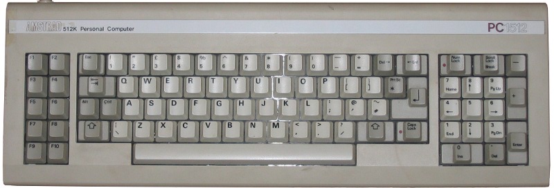
85-Key Keyboard
When Amstrad made their first PC clones, they didn't copy the original PC keyboard interface. Instead, their XTs use a custom interface with its own signalling system. At a hardware level, it's quite similar to the keyboard used on the earlier PCW8256, but with the keys rearranged into something closer to IBM's 84-key AT layout.
As with IBM's original XT keyboard, the PC1512 keyboard is built around an 8048 microcontroller, part number 40042.

Wiring
The keyboard socket is documented in the Technical Manual at section 1.15.5. Here's my own interpretation of it, showing the socket on the PC seen from outside.
Scancodes
These are the keycaps for the UK layout; you can find all layouts in the Technical Manual, Appendix 10.
The scancodes returned are as follows. Keys highlighted in green are unique to the PC1512; keys highlighted in blue are present on an IBM XT keyboard, but in different locations.
These scancodes are also shown in the Technical Manual, Appendix 9, but in decimal rather than hex.
In addition to the scancodes shown, the keyboard also includes a joystick socket. A joystick plugged into the keyboard sends the following scancodes:
| 0x77 | Fire 2 |
| 0x78 | Fire 1 |
| 0x79 | Right |
| 0x7A | Left |
| 0x7B | Down |
| 0x7C | Up |
If a mouse is connected to the main PC, its buttons pull the M1 and M2 lines low, and the keyboard generates scancodes for these as well:
| 0x7D | Right button |
| 0x7E | Left button |
Since the mouse buttons behave as keyboard keys, this means that any utility handling keyboard scancodes (eg, KEYB) must handle them correctly. Otherwise mouse clicks will not register.
Scancodes 0x71, 0x72, 0x73, 0x75 and 0x76 correspond to nonexistent positions in the keyboard matrix. It is possible to provoke the keyboard into generating them by pressing three other keys simultaneously. For example:
| 0x71 | NumLock + Keypad Enter + Keypad 5 |
| 0x72 | NumLock + Keypad Enter + Keypad 9 |
| 0x73 | NumLock + Keypad Enter + Scroll Lock |
| 0x75 | NumLock + Joystick up + Keypad 2 |
| 0x76 | NumLock + Joystick up + Keypad 1 |
Protocol
The wire protocol used by the keyboard is documented in the Technical Manual at section 1.15. There is a graph showing timings at kbdbabel.org, but note that the line "Exclusive communication from device to host" is incorrect; as mentioned in the Technical Manual, the host can signal that its buffer is full (by pulling the Data line low) or reset the keyboard (by pulling the Clock line low for at least 10ms).
This protocol appears to be the same as the one used by later Amstrad XT keyboards up to the PC3086; it is possible to connect a PC1512 keyboard to a 2086 or 3086 with a simple cable adaptor, though the BIOS on these computers doesn't know what to do with the small enter key, the Del-> key or the joystick. In addition, the keyboard has no connection for the keyboard lock.
John Elliott 30 August 2010