
IDEALISED TERMINAL TO TERMINAL CONNECTION
Fig 1
| Section 3 | Site Index | Book Index |
The two operating systems supplied with your PC1512, MS-DOS 3.2 and DOS Plus, both support a set of Mouse functions which allow a program to access the mouse and control the cursor. These functions can be called from within your application programs by using the software interfaces described below.
The mouse functions described in this appendix are as follows.
The DOS Plus operating system supports only the subset of mouse functions marked with the double asterisks built into the DOS Plus input/output system.
For the MS-DOS operating system, the program MOUSE.COM must be loaded by either typing "MOUSE" at the keyboard or by having a "MOUSE" line in your AUTOEXEC.BAT.
When MOUSE.COM is loaded, it performs an initialisation process and installs the mouse driver software into the system. Once installed, the mouse driver remains permanently resident until the next time you bootstrap your computer. After successfully completing initialisation, the following message is output to the display:
"--- Installing Mouse Device Driver V5.00 ---"
If the mouse driver fails to load you will get one of the two following messages:
During initialisation, the following actions take place:
The above initialisation applies only to MOUSE.COM in the MS-DOS environment. For DOS Plus which has a built in mouse driver, a similar initialisaiton takes place during system bootstrap. The basic ticker rate for DOS Plus is also 18ms (or about a 54Hz rate).
The general procedure for making an assembly language program call to the mouse function driver program is:
The cursor coordinates required for the various function calls are in the form of X-Cursor (horizontal) and Y-Cursor (vertical) values. The range of the X-Cursor is always the full 0 to 639 points of the high resolution graphics screen and the Y-Cursor ranges from 0 to 199. This coordinate system defines the "virtual" screen and when in modes with less resolution than 640 points then the least significant bits of the X-Cursor are ignored. In 4-Colour (320 x 200) graphics only even values are significant while in 80 column text mode only every eighth position is valid and in 40 column text modes only every 16th position is valid. Supplied values are rounded to the nearest values permitted for the current screen mode.
The standard unit of mouse motion is called the "mickey" and is equal to approximately 1/200 of an inch. See Mouse function 15 which sets the mickey to pixel ratios.
In Text Mode, mouse movement will cause cursor key tokens to be inserted into the keyboard buffer. The scaling factors read from the NVR during initialisation are used to determine how many units of mouse movement are to be sensed before a single cursor key token is inserted into the keyboard buffer. Invoking any Mouse Function except Function 0 or Function 2 will disable this extra mode (i.e. cursor movement tokens are not generated). Invoking Function 0 (Initialisation) enables this extra mode (i.e. cursor tokens are generated) and invoking Function 2 (Hide Cursor) does not change the current mode.
In Text Mode, the mouse buttons interrupt routine (interrupt 6) translates the Left and Right mouse buttons into the appropriate scan codes which are held in NVR bytes 29-30 (for Left) and 31-32 (for Right). The default NVR value for these scan codes is the ignore code (all F's). The NVRPATCH programs can be used to set the mouse button codes to handy values such as CR and ESC.
In Graphics Mode, the mouse buttons interrupt routine translates the Right mouse button to the shift key token, and the Left button is passed through as a mouse event to the user defined subroutine. (See mouse function 12.)
This function initialises the mouse driver and returns the current status of the mouse hardware and software.
CPU registers are used as follows:
Since the mouse hardware is verified by power-up testing the driver always returns a mouse status of true (-1). If the mouse driver is not resident then AX is returned as false (0).
Both MS-DOS and DOS Plus return the number of buttons as 1.
The mouse driver parameters are reset to the following values:
| Parameter | Value |
|---|---|
| Cursor Flag | Hidden (-1) |
| Cursor Position | Center Screen |
| Graphics Cursor | Arrow |
| Hot Spot | -1, -1 |
| Text Cursor | Inverting box |
| User Defined Call Mask | Zeros |
| Light Pen Emulation Mode | Enabled |
| Mickey to X-Pixel Ratio | 8 |
| Mickey to Y-Pixel Ratio | 16 (8 for DOS Plus) |
| Min/Max X-Cursor Position | 0/639 |
| Min/Max Y-Cursor Position | 0/199 |
The mouse X and Y hardware counters are reset and a number of internal software counters are zeroed.
The mouse driver is initialised to be in Text Mode (and cursor tokens are generated in response to mouse motion).
This function increments the Cursor Flag and, if the flag is zero, the cursor display is enabled.
CPU registers are used as follows:
This function decrements the Cursor Flag.
CPU registers are used as follows:
This function returns the state of the Left and Right buttons and the current cursor position.
CPU registers are used as follows:
The Button Status word returned in BX is a single integer value. Bits 0 and 1 represent the Left and Right buttons, respectively. A bit is set if a button is down and clear if it is up.
This function sets the cursor to the specified X-Cursor and Y-Cursor positions. The values must in range of the virtual screen. If the screen is not in high resolution mode, the values are rounded to the nearest values permitted for the current screen mode.
CPU registers are used as follows:
This function returns the current button status, a count of button presses since last call to this function, and the X-Cursor and Y-Cursor positions at the last button press.
CPU registers are used as follows:
This function returns the current button status, a count of button releases since last call to this function, and the X-Cursor and Y-Cursor positions at the last button release.
CPU registers are used as follows:
This function sets the minimum and maximum X-Cursor position. Subsequent cursor motion is restricted to the specified range.
CPU registers are used as follows:
If the cursor is outside the area when the call is made, it is set to just inside the area. If Minimum is greater than Maximum, the two values are exchanged.
This function sets the minimum and maximum Y-Cursor position. Subsequent cursor motion is restricted to the specified range.
CPU registers are used as follows:
If the cursor is outside the area when the call is made, it is set to just inside the area. if Minimum is greater than Maximum, the two values are exchanged.
This function defines the shape, colour, and center of the cursor for graphics mode.
CPU registers are used as follows:
The Hot Spot is a point relative to the upper left corner of the cursor block used to determine the cursor coordinates. Both coordinates must be in the range of -16 to +16.
The values in the screen mask and cursor mask are used to build the cursor shape and colour. The ES register contains the segment address of the screen and cursor mask array and DX is the offset to be applied to the ES register.
The screen and cursor masks are two 16- by 16-bit arrays arranged contiguously in memory. The screen mask determines whether the cursor pixel is part of the shape or part of the background. The cursor mask determines how the pixel under the cursor contributes to the colour of the cursor. To create the cursor, the mouse software first logically ANDs the screen mask with the 256 bits of data that define the pixels under the cursor. Then, it logically XORs the cursor mask with the result of the AND operation. The following truth table shows the relationship between the screen mask, the cursor mask, and the resultant screen memory.
| Screen Mask Bit | Cursor Mask Bit | Resultant Screen Bit |
|---|---|---|
| 0 | 0 | 0 |
| 0 | 1 | 1 |
| 1 | 0 | Unchanged |
| 1 | 1 | Inverted |
In high resolution (640 by 200) graphics mode each bit in the screen and cursor masks logically maps to one bit on the screen. In four colour (320 by 200) graphics mode each pair of bits correspond to one pixel.
This function selects the software or hardware text cursor and defines the attributes of the selected cursor.
CPU registers are used as follows:
If the software text cursor is selected CX & DX contain Screen and Cursor masks. The 16-bit masks are ANDed and XORed in the same manner as the graphics cursor operation and operate upon the character and attributes bytes of the character position of the cursor.
In both 40-column and 80-column text modes the 16-bits of screen data for each character take the following form:
| Bits: | 15 | 14..12 | 11 | 10..8 | 7........0 |
| Contents: | B | Backgnd | I | Foregnd | Character |
Where:
Refer to section 1.11 for the attribute byte details.
The screen and cursor masks are divided into the same fields as shown above so that the value of the masks defines the new attributes of the character when the cursor is over it. For example a screen mask of 077FFh and a cursor mask of 07700h would invert the foreground and background colours.
If the hardware cursor is selected CX & DX define the first and last scan line in the cursor shown on the screen.
This function returns the horizontal and vertical mickey count since the last call to this function. CPU registers are used as follows:
The "mickey" is the standard unit mouse motion equal to approximately 1/200 of an inch. See Mouse function 15 which sets the mickey to pixel ratios.
This function sets the call mask and subroutine address for the mouse interrupts. CPU registers are used as follows:
The mouse driver uses the ticker interrupt to poll the mouse hardware (at approx. 55 times per second) and when one of the events specified in the call event mask is noted your subroutine is called. The layout of the call event mask is:
| Bit | Event (1=Enabled) |
|---|---|
| 15-5 | Unused. |
| 4 | Right Button Released. (will never occur). |
| 3 | Right Button Pressed. (will never occur). |
| 2 | Left Button Released. |
| 1 | Left Button Pressed. |
| 0 | Cursor Position Changed. |
Note that calling mouse function zero (Initialisation) disables all events so that function 12 must be called again.
When calling your subroutine the CPU registers are loaded as follows:
This function enables the light pen emulation by the mouse. CPU registers are used as follows:
With the Light Pen Emulation on, the VDU I/O software interrupt (Int 16) returns mouse identification vice the normal light pen address information (See VDU Sub-Function 4).
This function disables the light pen emulation by the mouse. CPU registers are used as follows:
This function sets the mickey to pixel ratio for mouse motion. CPU registers are used as follows:
The X- and Y- ratios specify a number of mickeys per 8 pixels. The values must be in the range of 1 to 32767.
With a setting of 16 mickeys per 8 pixels horizontally it takes about 6.4 inches of mouse movement to move the cursor across the screen (640 pixels). With the same 16 mickeys per 8 pixels vertically it takes about 2 inches of travel to move the cursor the full vertical deflection (200 pixels).
This function defines a region on the screen for updating. CPU registers are used as follows:
The mouse cursor is hidden while the screen is being updated and a call to function 1 is needed to show the cursor again.
Function 16 is similar to function 2 (Hide Cursor) bit is for advanced applications which require quicker screen updates.
This function defines the threshold speed for doubling the cursor's motion on the screen. CPU registers are used as follows:
This function makes it easier to point at images widely separate on the screen.
A threshold value of zero sets a value of 64 mickets.second. Setting a large value (such as 32767) disables the double speed threshold.
The MS-DOS operating system allows for a number of installation specific configuration options during the system startup progress through the use a file called CONFIG.SYS when it is found in the root directory of the startup disk. These configuration options include the following commands:
The CONFIG.SYS can be created with any text editor and the simple screen editor RPED is ideal for this purpose.
This command enables the MS-DOS extended break checking to be either set or reset. Normally, MS-DOS checks to see if CTRL-C has been typed while it is reading from the keyboard, writing to the screen or a printer. Setting Break to 'on' allows CTRL-C checking to be extended to other functions such as disk reads or writes. The syntax of the BREAK command is:
If no field is specified then OFF is assumed (as the default value).
This command allows you to specify the number of buffers that MS-DOS allocates when it starts up. A disk buffer is a block of memory where MS-DOS holds data being read from or written to a disk when the amount of data is not an exact multiple of sector size.
The syntax of the BUFFERS command is:
Where 'n' is a number between 1 and 99. If the BUFFERS command is not used then MS-DOS defaults to 2 buffers. The number of buffers remains in effect after bootstrap until the machine is switched off or bootstrapped again.
The country command is used to select the country dependent information as shown in appendix 3.
The syntax of the country command is:
Where 'nnn' is the 3-digit country (Num) code from Appendix 3. Note that only the information in the table is affected and other country dependent factors such as the language links, N-Utility setup, KEYBxx, and national variant disks affect the total country dependent environment.
This command installs the device driver in the specified pathname to the system list.
The syntax of the DEVICE command is:
The file specified is loaded and given control. The driver may then perform the necessary steps to configure itself and the system for its operation. See the MS-DOS Technical Reference Manual for information on how to create your own device driver.
Your MS-DOS disk (Disk 1) contains two installable device drivers, DRIVER.SYS, and RAMDRIVE.SYS which can be used for variable device configurations.
If you plan to use the ANSI escape sequences described in the PC1512 users manual, you would need to include the following command in your CONFIG.SYS file:
This command causes MS-DOS to replace all keyboard input and screen output support with the ANSI escape sequences.
Note that the Amstrad disc is supplied with a version of ANSI.SYS that conforms with the NVR value (byte 36) for screen colouring and which refrains from blanking the screen unnecessarily when scrolling.
DRIVER.SYS is an installable device driver that supports external drives. To install DRIVER.SYS, include the following command in your CONFIG.SYS file:
Where:
and optionally:
RAMDRIVE.SYS is an installable device driver which enables the usage of a portion of the computer's memory as though it were a disk drive. This area of memory is referred to as a RAM disk or a virtual disk.
If you have extended memory installed starting at the 1MB boundary or if you have an extended memory which meets the LIM [Lotus(R)/Intel(R)/Microsoft(R)] Expanded Memory Specification, you can use this memory for one or more RAM disks. Otherwise RAMDRIVE.SYS locates RAM drives in low memory.
To install RAMDRIVE.SYS, include the following command in your CONFIG.SYS file:
Where:
The DRIVPARM command allows overriding of the device parameters for a specific logical drive.
The syntax is:
Where:
and optionally:
This command allows the overriding of default system parameters for a particular logical drive. This information would be used by the commands which create new diskettes (such as FORMAT and COPY) when writing out the directory and FAT (File Allocation Table) information. For any physical device which is read the information in the FAT ID is used when determining device characteristics.
The FCBS command allows you to specify the number of file control blocks available to the system and consequently the number of files which can be opened at any one time.
The syntax of the FCBs is:
Where <x> is the number of FCBs (in the range of 1 to 255) to allocate and <y> is the number of FCBs protected from closure when a program tries to open more than <x> files. The first <y> files opened will be protected. MS-DOS selects the least recently used (non-protected) FCB when it must automatically close a file.
If the FCBS command is not used MS-DOS defaults <x> and <y> to 4 and 0 respectively. It is an error to set <y> greater than <x>
The FILES command specifies the maximum number of file handles that can concurrently be opened. When a program opens a file or a device it is assigned an identifier or "handle" which can be used by that program in referring to the file.
The syntax of the FILES command is:
Where 'n' is the number of handles in the range of 8 to 255. When no FILES command is used MS-DOS assumes a default value of 8. Any value higher than 20 serves no useful function.
The LASTDRIVE command is used to set the maximum drive letter which MS-DOS will accept.
The syntax of the LASTDRIVE command is:
Where 'd' is any letter from A to Z (and is case insensitive). When the drive letter is lower than the actual physical drives then MS-DOS ignores the LASTDRIVE specification and uses the default value which is the letter 'E'.
The SHELL command is used to specify an alternate top-level command processor in place of the standard COMMAND.COM file.
The syntax of the SHELL command is:
This command is used in conjunction with major software packages which furnish their own command processors. The MS-DOS technical manual contains information on developing command processors.
When this command is invoked, a resident keyboard interrupt process is installed which replaces the ROS keyboard interrupt process. UK specific characters £, #, @, &, " are mapped to their respective keys. The system available memory will decrease by the resident size of keybuk. Pressing [CTRL] + [ALT] + [F1] restores the ROS keyboard processing and pressing [CTRL] + [ALT] + [F2] resets back to KEYBUK keyboard input.
Note that the PC1512 is supplied with a special version of keybuk which correctly handles the extra key codes generated by the [DEL->] & [ENTER] keys, the joystick port and the two mouse buttons. Using any other version of KEYBUK will render all these keys inoperative.
| Country | Num | DtF | DtS | TmS | TmF | CSm | CFt | CSd | ThS | DeS | DlS |
|---|---|---|---|---|---|---|---|---|---|---|---|
| Australia | 061 | 1 | - | : | 1 | $ | 0 | 2 | , | . | , |
| Belgium | 032 | 1 | / | : | 1 | F | 3 | 2 | , | ; | |
| Canada | 002 | 2 | - | : | 1 | $ | 3 | 2 | , | ; | |
| Denmark | 045 | 1 | / | . | 1 | DKR | 3 | 2 | . | , | ; |
| Finland | 358 | 1 | - | : | 1 | MK | 3 | 2 | , | ; | |
| France | 033 | 1 | / | : | 1 | F | 3 | 2 | , | ; | |
| Germany | 049 | 1 | . | . | 1 | DM | 0 | 2 | . | , | ; |
| Italy | 039 | 1 | / | : | 1 | Lit | 1 | 0 | . | , | ; |
| Israel | 972 | 1 | / | : | 1 | ö | 2 | 2 | , | . | , |
| Middle East | 785 | 1 | / | : | 1 | $ | 3 | 3 | . | , | ; |
| Netherlands | 031 | 1 | - | : | 1 | ƒ | 0 | 2 | . | , | ; |
| Norway | 047 | 1 | / | . | 1 | KR | 2 | 2 | . | , | ; |
| Portugal | 351 | 1 | / | : | 1 | $ | 4 | 2 | . | , | ; |
| Spain | 034 | 1 | / | : | 1 | Pt | 3 | 2 | . | , | ; |
| Sweden | 046 | 2 | - | . | 1 | SEK | 2 | 2 | . | , | ; |
| Switzerland | 041 | 1 | . | . | 1 | Fr | 2 | 2 | , | . | , |
| United Kingdom | 044 | 1 | - | : | 1 | £ | 0 | 2 | , | . | , |
| United States | 001 | 0 | - | : | 0 | $ | 0 | 2 | , | . | , |
Table Columns:
| Num | = | Country Number Code. |
| DtF | = | Date Format. (0 = U.S. M/D/Y, 1=EURO D/M/Y, 2 = JAPAN Y/M/D) |
| DtS | = | Date Separator. |
| TmS | = | Time Separator. |
| TmF | = | Time Format. (0=12-hour clock, 1=24-hour clock) |
| CSm | = | Currency Symbol. |
| CFt | = | Currency Format. (Bit 0: 0 = Currency symbol Precedes/1=Follows Field, Bits 1 & 2: Number of spaces between Value & Symbol) |
| CSd | = | Number of significant decimal digits in currency. |
| ThS | = | Thousands Separator. |
| DeS | = | Decimal Separator. |
| DlS | = | Data List Separator. |
For a complete understanding of the connections required between the RS232C and the outside world, it is important to realize that all devices with a serial interface can be classified as either a modem or as a terminal. Modems are merely a way of extending the length of the connection (often via a terminal wire) between two terminals. Fig 1 (below) shows a simplified, idealised terminal to terminal connection through modems.

IDEALISED TERMINAL TO TERMINAL CONNECTION
Fig 1
The standard connector used for serial interfaces has 25 pins although only up to seven are required in most cases. When connecting to a modem a 'one-to-one' cable is used, i.e. pin 1 to pin 1, pin 2 to pin 2, ... pin 25 to pin 25. Assuming such cables are in use, data is transferred as follows:
Following the signal path from left to right (in Fig 2), characters from the keyboard are sent as serial data patterns out of pin 2 of the left-hand terminal, to pin 2 of the modem (the connection marked 'transmit data'). The left-hand modem sends the characters via the telephone line, to the right hand modem. The characters are received pin 3 of the right hand modem (the connection marked 'receive data') which sends them to pin 3 of the right-hand terminal. On receipt of the characters, the right-hand terminal displays them on the screen.
Notice how the names of the connections 'transmit data' and 'receive data' are expressed from the view point of the terminals and not the modems.
The data path from left to right just described, is exactly matched by a data path from right to left which uses the same numbered connections, i.e. pin 2 from the right-hand terminal it its modem (transmitting), and then to pin 3 of the left-hand (receiving) modem to the terminal. This arrangement is perfectly symmetrical, and there is no confusion over who is using which pin number and for what direction of data transfer.

Fig 2
Problems of definition arise, howeve, when we wish to connect two terminals together locally, without the intervening pair of modems. We cannot connect pin 2 to pin 2 because both keyboard will be transmitting head-on and neither screen is connected to anyone who is sending. The obvious solution is to cross over pins 2 and 3 so that the transmit pin of each terminal is connected to the receive pin of the other. A cable containing such a cross-over connection is known as a 'Null-modem' cable because of the way in which in replaces the pair of back to back modems.
The earth pin (pin 7) is still common to both terminals using this arrangement.
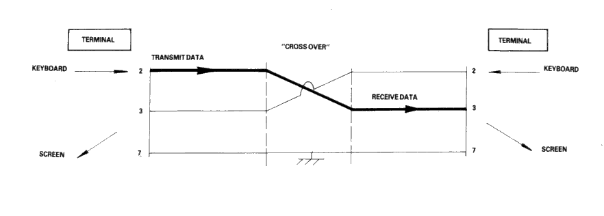
Fig 3
Naturally, the Amstrad PC1512 with its RS232C interface is considered a terminal, and therefore to connect to a modem (for example, to dial-up a database) requires a simple one-to-one cable.
The Null-modem cable is required for connecting to other terminals. The sort of equipment we mean by terminals is: a second Amstrad computer plus RS232C, a conventional Visual Display Unit (VDU), a printer with a serial interface, or any other serial interface device.
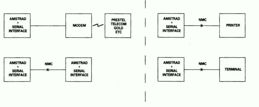
Fig 4
There is a point to be noted here: many manufacturers of devices such as desk-top computers wire up their serial interface (for VDU or a Printer) as if it were a modem, not a terminal. This is in the belief that life will therefore be simpler because VDU's and printers can connected to that computer with one-to-one cables.
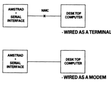
Fig 5
In a perfect world, it would be possible to identify which serial devices behave like modems and which ones behave like terminals by examining the 'sex' of the 25-way connector - terminals should have a 'male' connector, and modems a 'female' connector. This is not, unfortunately, as reliable a guide as it should be, as many manufacturers of terminals and printers equip them with 'female' connectors, mostly for reasons of electrical safety.
If in doubt, the ultimate test is to examine the user manual and determine the function of PIN 2 - if the description includes the word 'TRANSMIT' then the equipment is wired as a terminal, and if it includes the word 'RECEIVE' then the equipment is wired as a modem.
The simplified connection described so far does not allow any control of the data flow. In practice, we often with the receiving device to have control over the transmitting device, thus preventing the receiving device from being overwhelmed (where it is slower in using the input than the rate at which the input is arriving). In addition, if the transmitting device has reason to mistrust the data which it is sending, there should be some provision for it to disable the receiving device.
In the case of modem to terminal connection; when the terminal is able to transmit it activates pin 4 - the RTS pin (Request To Send). When the modem is ready to receive input it activates pin 5 - the CTS pin (Clear To Send). The terminal will only send when CTS is activated. Thus the modem can control the flow rate using CTS.
When the modem considers that the data which it is about to send is suitable, it activates pin 8 - the DCD pin (Data Carrier Detect). When the terminal is ready to receive input it activates pin 20 - the DTR pin (Data Terminal Ready). The modem will only transmit when DTR is activated. Thus the terminal can control flow rate using DTR.
There are two further signals which must be introduced here. One is on pin 22 - the Ring indicator, which simply allows the modem to tell the terminal that the phone is ringing (at which point software in the terminal might be expected to wake up). The other signal is on pin 6 - DSR (Data Set Ready). This signal is ignored by the receiving side of the RS232C; the modem will activate this signal at much the same time that it activates DCD, and therefore no functionality is lost by ignoring DSR.
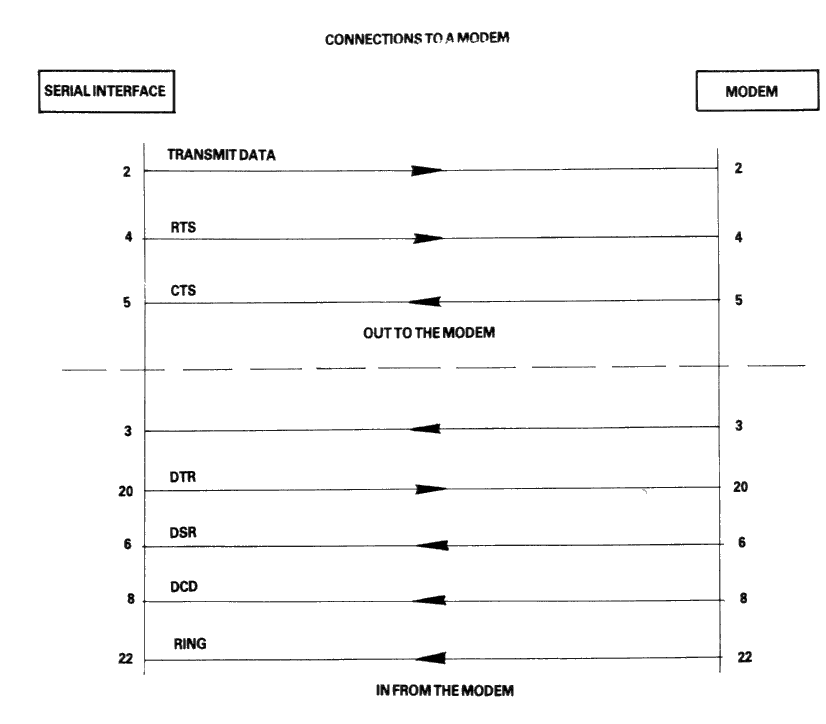
Fig 6
In the case of terminal-to-terminal conenctions, the Null-modem cable must be used with the additional connections to pins 2, 3, and 7 as already discussed. The full Null-modem cable swaps pins 4 and 8 - the RTS/DCD 'I am happy to send' signals, and pins 20 and 5 - the DTR/CTS 'busy' signals. To be on the safe side, pin 6 (DSR) is connected to pin 8 (DCD) in case that end of the cable is ever connected to a terminal which is fussy and requires DSR as well as DCD.
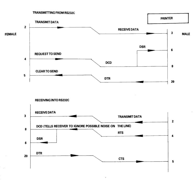
Fig 7
There is a school of thought which says that a Null-modem cable, unlike the pair of modems it replaces, is ALWAYS 'happy to send'. Therefore it is quite in order to generate DCD (and DSR) permanently. This is achieved by connecting them to the RTS at the same end of the cable, rather than to the RTS at the other end of the cable.
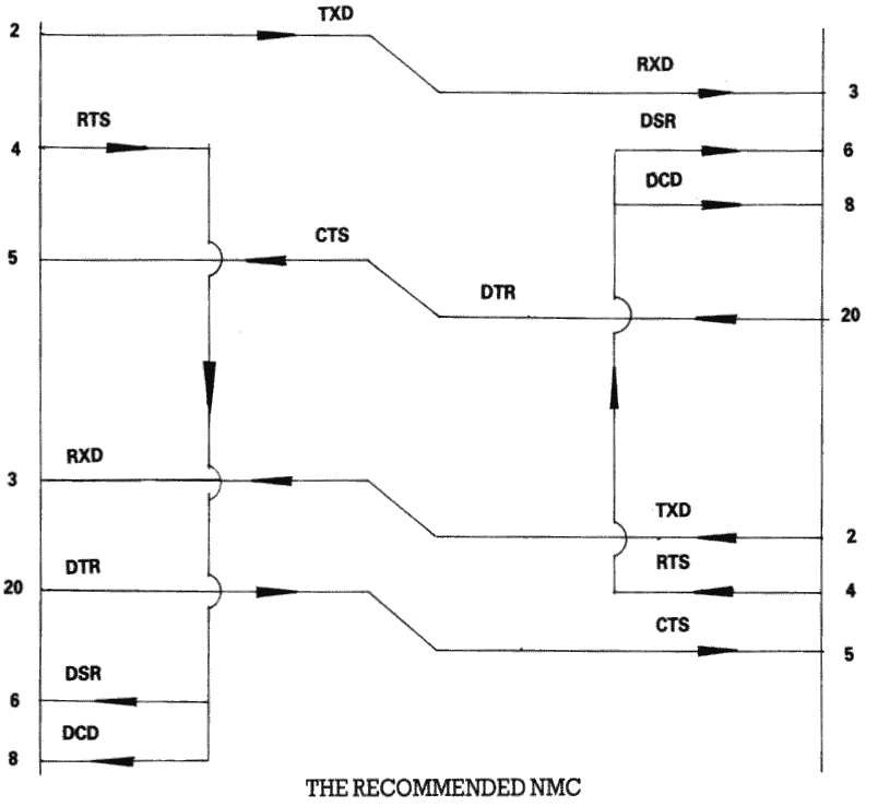
Fig 8
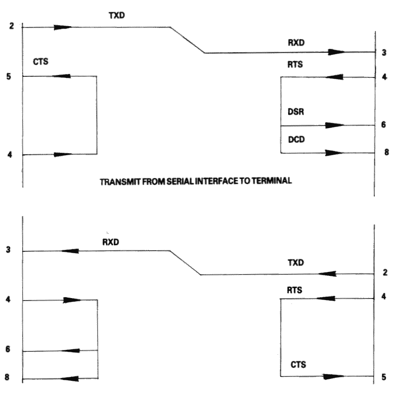
Finally, if the transmission rate from one of the two terminals is known to be unstoppable (e.g. a person typing at the keyboard), or is so slow and infrequent (e.g. the software handshake characters 'XON, XOFF' sent by the printer) that there is no danger of over-running the receiving end, then it is permissible to permanently enable the transmission by linking pin 5 (CTS) to pin 4 (RTS), i.e. to always send if ready (at the transmitting end of the cable). It may well be facilitated in any case, for the transmitting terminals to ignore the state of CTS under these circumstances.
THE RECOMMENDED TERMINAL CABLE
Fig 9
| Line Name | Computer Connector | Printer Connector |
|---|---|---|
| Strobe | 1 | 1 |
| Data Bit 0 | 2 | 2 |
| Data Bit 1 | 3 | 3 |
| Data Bit 2 | 4 | 4 |
| Data Bit 3 | 5 | 5 |
| Data Bit 4 | 6 | 6 |
| Data Bit 5 | 7 | 7 |
| Data Bit 6 | 8 | 8 |
| Data Bit 7 | 9 | 9 |
| Ack | 10 | 10 |
| Busy | 11 | 11 |
| PO | 12 | 12 |
| Slct Out | 13 | 13 |
| AutoFd | 14 | 14 |
| Error | 15 | 32 |
| Reset | 16 | 31 |
| Slct In | 17 | 36 |
| GND | 18 | 19 |
| GND | 19 | 20 |
| GND | 20 | 21 |
| GND | 21 | 22 |
| GND | 22 | 23 |
| GND | 23 | 24 |
| GND | 24 | 25 |
| GND | 25 | 26 |
| GND | 27 | |
| GND | 28 | |
| GND | 29 | |
| GND | 30 | |
| GND | 33 | |
| GND | 15 | |
| GND | 16 | |
| GND | 17 | |
| GND | 18 | |
| GND | 34 | |
| GND | 35 |
The following is a summary of the power supply requirements for the Amstrad PC 1512.
Main Electronics Board (Including Keyboard)
Expansion Slots Allowance (Three Slots)
Floppy Disc Drive (Single)
Hard Disc Drive
This results in the following total for a worst case configuration:
System with 2 floppy drives and Hard Disc
Use 18 pcs 64K - 150 ns Drams plugged into 18 I.C. sockets provided, numbered IC153 to IC170 on main pcb. A link switch must then be moved into the 640K position. (see link diagram). It is important that this switch position is changed before unit is switched on. Please note if 2nd drive has been fitted, it needs to be removed while adding the extra memory.
![[Diagram showing motherboard]](a171.png)
![[Character set]](a181.png)
![[Keycodes diagram]](a191.png)
![[USA and UK layouts]](a1a1.png)
![[French and German layouts]](a1a3.png)
![[Spanish and Italian layouts]](a1a5.png)
![[Swedish and Danish layouts]](a1a7.png)
| Section 3 | Site Index | Book Index |