PC1512 display notes
The PC1512 built-in display adaptor is an emulation of IBM's CGA. Unlike a real CGA, it is not built around a real MC6845 controller, and so attempts to get custom video modes out of it may not work as expected. Its 640x200 CGA mode can be set up to be a 16-colour mode rather than mono.
If you program it with BIOS calls, the PC1512 behaves just like a real CGA, except:
- Since the PC1512 cannot output to a composite monitor, there is no difference between the 'greyscale' text modes (0 and 2) and the 'colour' ones (1 and 3). On a colour monitor both are in colour; on a mono monitor both are in greyscale.
- Mode 5 (the 'greyscale' graphics mode) displays in colour, using an alternative colour palette: Cyan, Red and White.
The undocumented 160x100x16 "graphics" mode works correctly.
Fonts
The PC1512 supports up to 4 fonts for CGA text mode, selectable using option links on the motherboard. A Version 1 PC1512 has two fonts; a Version 2 PC1512 has three.
| Normal |  |
|---|---|
| Danish | 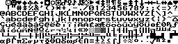 |
| Greek (PC1512 v2 only) | 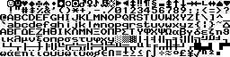 |
Technical information
The PC1512 graphics adaptor has some extra ports which are not present on standard adaptors. One of the bits in the mode control register also behaves slightly differently:
Mode control register: 03D8h
On a genuine CGA, bit 2 of this register selects greyscale (as opposed to colour) mode when using a composite monitor. On the PC1512, which does not support composite monitors, it is ignored in text and 640x200 modes, but is used in 320x200 mode. If it is set and the green/red/yellow palette is selected, then the cyan/red/white palette is used instead.
Documented in the technical manual, section 1.11.3.1.
Colour select register: 03D9h
In 640x200 graphics mode, this is used to select which colour planes to display. The ROS initialises it to 7, so that the Red, Green and Blue planes are shown and the Intensity plane isn't.
- Bit 0 for Blue
- Bit 1 for Green
- Bit 2 for Red
- Bit 3 for Intensity
Documented in the technical manual, section 1.11.3.2.
Colour plane write: 03DDh
This is a write-only port which is used to select which planes to write to in the 640x200 graphics mode. The ROS initialises this to 0Fh so that all four planes are written together.
The value written is a bitmap of planes to write:
- Bit 0 for Blue
- Bit 1 for Green
- Bit 2 for Red
- Bit 3 for Intensity
Documented in the technical manual, section 1.11.3.3.
Colour plane read: 03DEh
This is a write-only port which is used to select which plane to read from in the 640x200 graphics mode. The ROS initialises this to 0 so that the blue plane is read.
Only the bottom 2 bits of this port have an effect - write:
- 0 for Blue
- 1 for Green
- 2 for Red
- 3 for Intensity
Documented in the technical manual, section 1.11.3.4.
Border: 03DFh
This is a write-only port which is used to set the border colour in the 640x200 graphics mode.
- Bit 0 for Blue
- Bit 1 for Green
- Bit 2 for Red
- Bit 3 for Intensity
Documented in the technical manual, section 1.11.3.5.
CRTC registers
The PC1512 does not emulate most of the MC6845 registers:
- Registers 0, 2-5 and 7-8 are completely ignored.
- Registers 1 and 6 should be non-zero but are otherwise completely ignored.
- Registers 9-17 behave as normal.
Documented in the technical manual, section 1.11.5.
Using the 640x200x16 graphics mode
The normal procedure to use the 640x200x16 graphics mode is:
- Select ROS graphics mode 6.
- Disable interrupts.
- Wait for frame flyback.
- Set bit 4 of port 03D8h (should have been done already by the mode set).
- Write 0Fh to the colour select register at 03D9h so that all 4 planes are shown.
- Select the required planes by writing to port 03DDh.
- Start writing to screen memory.
John Elliott 23 August 2003