                8.  THE TELCOM PROGRAM

The TELCOM program is designed to allow the M10 to communicate with other
computers,  either  by  transmitting  and receiving data over a telephone
line or by direct connection.  In this  program,  more  than  any  other,
there  are major differences between the M10 MODEM and the models without
this facility. All the functions and operations described in this chapter
are available to the M10 MODEM.

For the user's convenience,  the  table  in  Figure  8-1  summarises  the
differences  between  the  M10 MODEM and the other models for the various
connections and operations of the TELCON  program.   It  also  lists  the
required accessories for all of these options.  Thus the user can tell at
a glance which operations ace available with his model and which  access-
ories are needed.
| 810 MODEM | M10 WITHOUT MODEM | |
| Direct connection to a telephone line Modem cable | Not possible | |
| Auto-dialling | Modem cable | Not possible |
| Manual dialling from keyboard | Modem cable | Not possible |
| Automatic log-on to host computer | Modem cable | Not possible |
| Data exchange by telephone with a host computer |
Modem cable or acoustic coupler |
Combined acoustic coupler/modem |
| Direct connection to another computer |
Null modem connecting cable (cross cable) with straight cable for gender change |
Null modem connecting cable (cross cable) with straight cable for gender change |
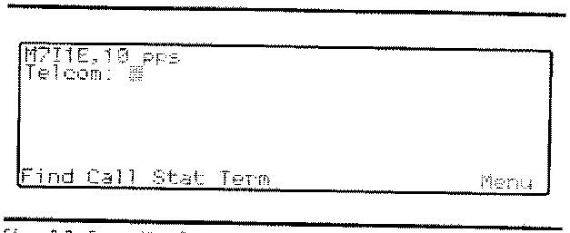
 Fig. 8-2 Screen When TELCOM is Called
The code which appears on the first line of the display is a list of the
telecommunications parameters which are discussed in some detail later in
this chapter. On the second line is the TELCOM pronpt. The bottom line
displays the definition of the function keys on entering TELCOM.
TELCOM operates in two different modes, Entry and Terminal. On first
accessing the program it is automatically in Entry mode. In each of
these modes the function keys F1-F8 have different definitions and uses.
Entry mode is essentially for using the auto-dialling option while Termi-
nal mode is for data exchange with another computer. The two modes can
be used in sequence by the M10 MODEM to give an automatic dial and log-on
option. In such a sequence, Terminal mode is entered automatically as
part of the procedure; otherwise it is necessary to enter Terminal mode
manually by means of the function key F4.
CONNECTING THE M10 TO A TELEPHONE LINE
The M10 can be connected to a telephone line, either directly or through
an acoustic coupler. In the M10 MODEM version, both options are open. A
special modern cable is used to make the direct connection to a modular
telephone line and a simple acoustic coupler is used when linking the
computer to the line via the receiver. In all other versions, the con-
nection must be made through a combined acoustic coupler/modem in order
to use the data communications facility offered by the TELCOM program.
These three accessories - modem cable, acoustic coupler and combined
acoustic coupler/modem are all available from your Olivetti dealer. It
is particularly recommended to use the Olivetti MC 10 Modem Coupler, spe-
cially designed for data coromunicatiois using the M10 without integrated
modem. A detailed description of this device is given in Appendix C.
8-2
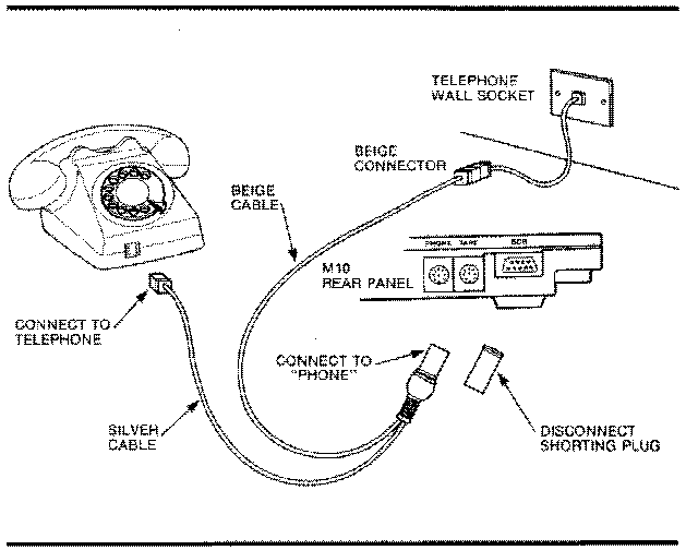
 wall connection.
3. Plug the connector you have just renoved from the handset (and which
goes to the wall socket) into the beige box at the end of the beige
cable.
4. Remove the shorting plug from the other end of the modem cable and
insert the round connector into the socket marked PHONE on the rear
panel of the M10.
5. Set the DIR/ACP switch on the underside of the M10 MODEM to DIR.
6. The M10 MODEM is now connected for data exchange by telephone with
another computer.
If you do not need the telephone handset, simply connect the beige cable
directly to the telephone wall socket. Tf you wish to use the telephone
normally without undoing all the connections, remove the modem cable from
the PHONE socket on the M10 MODEM and attach the shorting plug to the
connector.
Sometimes it is not possible to detach the line from the back of the
telephone handset (in hotel cooras, for example). In this case you must
use the acoustic coupler.
1. Connect the end of the coupler to the PHONE connector on the rear
panel of the M10 MODEM.
2. Fit the cups of the acoustic coupler to the receiver so that the
coupler speaker is over the telephone microphone and the coupler
microphone over the telephone speaker.
3. Set the DIR/ACP switch to ACP.
If you have the choice, always use the direct connection for a better and
more reliable exchange of data.
Note that the auto-dialling option is not available when the acoustic
coupler is used.
In all models of the 810 without inteqrated modem, it is necessary to use
a combined acoustic coupler/modem in order to exploit TELCOM to the full.
The Olivetti MC 10 Modem Coupler is the ideal equipment for this applica-
tion. In this case, set up the the M10 for remote communication using the
MC 10 as follows:
1. Connect the MC 10 cable to the RS-232C connector on the rear panel of
the the M10.
2. Ensure that the CAL/ANS switch on the underside of the MC 10 is set
to CAL.
3. Turn the power ON/OFF switch on the MC 30 to the ON position. The
indicator lamp will show a green flashing light.
The M10/MC 10 combination is now ready for connection to a telephone.
8-4
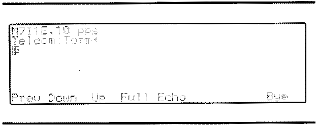
 THE FUNCTION KEYS IN TERMINAL MOOE
As can be seen, the function keys F1-F8 now control different functions
from those effective in Entry mode. Unlike the functions available in
Entry mode, those in Terminal mode are identical for all models of the
M10. They are:
F1 (Prev) - Pressing this key enables you to view the previous eight
lines of text on the screen when in Terminal mode. To
return the display to its original position, press <F1>
again.
F2 (Down) - The purpose of this key is to save or 'download' incom-
ing data from a host computer to a file for subsequent
viewing. When you press <F2>, the following prompt
appears on the screen:
File to Download?
Type in the name of the file to which the data are to be
saved and press <ENTER>. To stop downloading press <F2>
again.
F3 (Up) - The purpose of this key is to allow you to send a file
of data which you have prepared in advance for transmis-
sion to the host computer. When you press <F3>, the
prompt:
File to upload?
will appear on the screen. Type in the name of the pre-
viously prepared file that you wish to send and press
<ENTER>. This brings up the prompt:
Width?
The response to this prompt determines the maximum
number of characters the M10 will send before inserting
a carriage return and can have any value between 10 and
132.
F4 (Full/Half) - This key switches the transmission between Full Duplex
and Half Duplex. In Full Duplex mode, required by most
host computer systems, the characters are transmitted to
the host before appearing on the screen. In this way,
you know that the character has been accepted by the
host as soon as it appears on the screen. In Half
Duplex, the characters appear on the screen and are
transmitted simultaneously so there is no guarantee that
what you read on the screen is in fact what the host
computer has received. A noisy telephone line, for
example, can distort the transmission.
FS (Echo) - By connecting a printer to the M10 and pressing <F5>,
you will obtain a hard copy of what is displayed on the
screen. Thus you can retain a printed record of the
8-8
| PARAMETER | POSSIBLE VALUES | MEANING |
| Baud Rate | M 1 2 3 4 5 6 7 8 9 | Modem (300 baud) 75 baud 110 baud 300 baud 600 baud 1200 baud 2400 baud 4800 baud 9600 baud 19200 baud |
| Word Length | 6 7 8 | 6 bits 7 bits 8 bits |
| Parity | 0 E N I | Odd Even No Parity Ignore Parity |
| Stop Bit | 1 2 | 1 Stop bit 2 Stop bits |
| Line Status | E D | Enable Disable |
| Dial Pulse Rate | 10 20 | 10 pps 20 pps |